

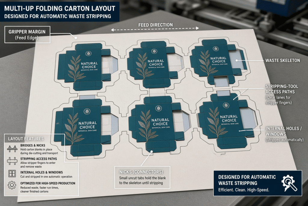
The automatic stripping performance is determined before a sheet arrives at the stripping station. Automatic waste stripping carton layout design is the process through which holes, windows, waste bridges, perimeter skeleton, gripper margin, carton spacing and other factors are set, and they all contribute to the control of waste pieces during the cutting process so that there is no marking of the blanks and no waste remains in the machine. An efficient layout in terms of screen may result in a number of isolated waste islands, narrow channels or conflicts between grippers and edges which leads to lowered velocity, manual collection or unstable delivery.
It is important for packaging engineers, the die makers and production teams to consider the imposed sheet as a manufacturing plan, and not just a graphic arrangement. Designing how waste is going to be held, contacted, released and cleared will eliminate many of the issues that arise on the floor at a later stage.
Why Carton Layout Matters Before the Stripping Station
The physical relationships that the layout establishes is the only one that can be used at the stripping station. Sheet control areas, bridges or nicks, outer skeleton waste, internal waste and finished carton blanks are left on the sheet after die cutting. Only the waste areas that are accessible and can be controlled are used for tooling. There are thus layout choices to be made that determine if the waste remains stable during transport, separates when desired, and doesn’t cause damage to nearby panels.
From Dieline to Imposed Sheet: The Manufacturing Path
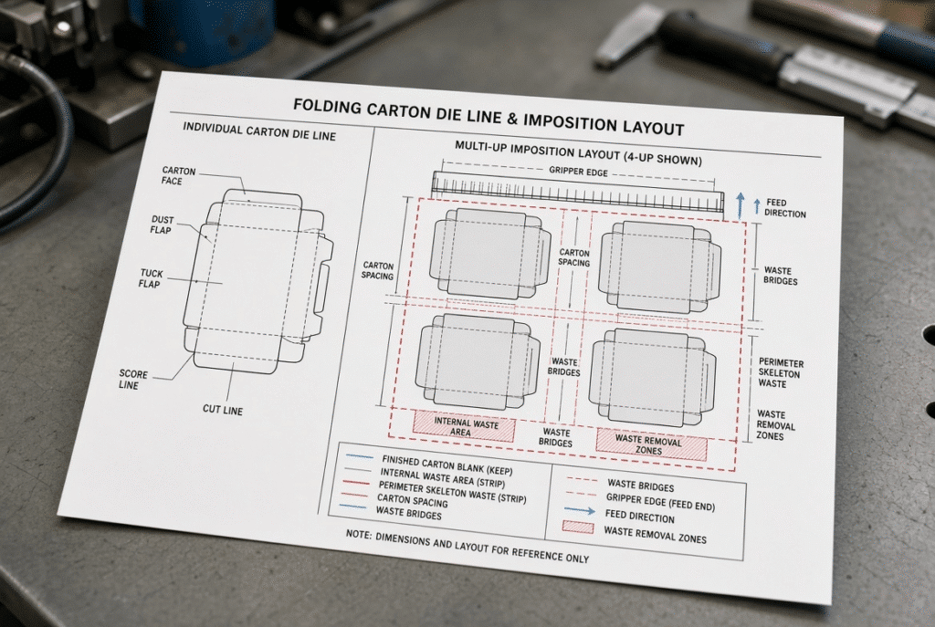
Panel, cut, crease, window, hanging hole, locking slot and tabs are all identified by the individual carton dieline. The imposed sheet then loads a number of cartons on the production blank, allowing for the setting of spacing, the waste channels, the feed direction and the position of the gripper-edge. Narrow waste strips or locating critical holes near the gripper edge can occur on a dieline that runs cleanly as one piece when it is nested multi-up. So it is important that the feasibility be checked at the imposed-sheet level other than on the single-carton drawing.
Waste Must Be Held, Contacted, Released, and Cleared
There are four physical conditions that must be met for reliable automatic waste stripping. Control of waste is required in cutting and transporting the sheets. The aim of tooling is to be in contact with the waste but not with the finished carton surfaces. Waste should be able to be released at the designated stripping point. When removing pieces, they should be clear of the sheet and delivery area. A waste fragment can fail at any one of these components, if it is too small, too narrow, too close to a crease, or poorly connected.
Internal Holes, Windows, and Cut-Out Geometry
Common carton features include internal holes, displaying windows, hanging holes, narrow slots, ventilation slots, locking cut-outs and decorative shapes. They also often cause stripping problems. Irregular or small internal waste pieces provide only a small surface and a limited space for the clearance of pins or stripping tools on the lower position.
Small Holes and NarrowSlots Need Tooling Access
Narrow slots and small holes provide minimal clearance openings and allow for minimal stripping pin access. If the waste is positioned near an edge of the carton or a crease, or a print sensitive surface or other cut-out, the tooling might not have safe access without incurring marks. The early review of pin positioning and the properties of the materials is essential for hanging holes in retail cartons, locking slots in pharmaceutical packs, and decorative windows on cosmetic packs. The feasibility is not necessarily dependent on the minimum size; it is a function of the board grade, tooling system and machine configuration.
Irregular Windows and Decorative Cut-Outs Can Create Unstable Waste
If the stripping plan does not consider the direction of stripping, complex outlines may be twisted, folded, broken or remain partly connected. There may be weak zones within an irregular shape that are not affected similarly to a single round or rectangular cut-out. These shapes are known to the die maker and stripping-tool supplier before the design enters into full production tools.
Keep Sensitive Carton Features Clear of Stripping Contact Zones
If carton edges come into contact with waste removal mechanisms or any crease lines, foil areas, embossing, printed graphics and fine structural tabs may be damaged. Enough room should be left for pins, support and clearance areas. The aim is not to remove any features of the design but to preserve them until the waste is taken away.
Waste Bridges, Nicks, and Perimeter Waste Design
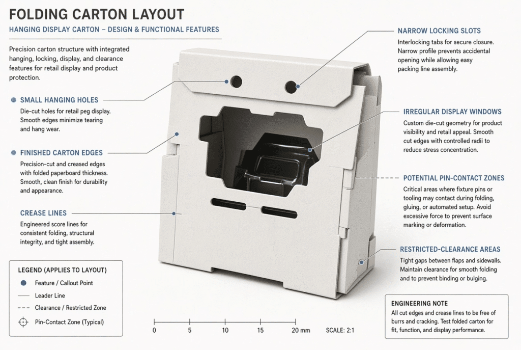
Bridges and nicks control how waste and carton blanks stay connected through die cutting, stripping, and sheet transfer. The right strategy keeps waste stable until the stripping action occurs, then allows predictable separation. Perimeter waste must be treated as part of the same controlled structure. If it breaks too early it interferes with transport; if it stays too strongly connected it resists stripping or demands manual cleanup.
Why Waste Bridges Must Balance Holding and Release
Bridges need enough strength to keep waste controlled as the sheet moves, yet not so much strength that the stripping tool cannot remove it cleanly. Location matters as much as strength because it influences how waste bends, tears, or releases. A long perimeter strip may need strategic connections to stay intact until the stripping station, while a small internal piece may need a bridge position that allows controlled release without tearing the finished carton.
Outer Skeleton Waste Must Remain Manageable
Outer skeleton waste is often larger than internal waste, yet it still creates problems when it is too weak, too fragmented, poorly supported, or difficult to guide away from the sheet. Design must consider stripping direction, gripper edge, carton spacing, and delivery route. Successful removal means more than detaching the waste; it also means preventing the waste from being carried into delivery, accumulating inside the machine, or mixing with finished blanks.
Avoid Creating Isolated, Unsupported Waste Islands
Isolated waste islands—small pieces surrounded by cuts or weak connections—can detach early, remain trapped, or require highly specific tooling that lengthens setup. The carton layout, board grade, die-cut quality, and stripping method must be evaluated together before deciding whether such an area is practical for automatic removal.
Gripper Margin, Feed Direction, and Sheet Stability
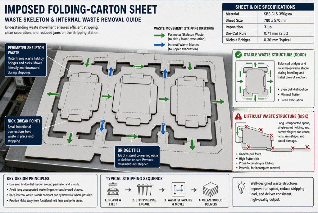
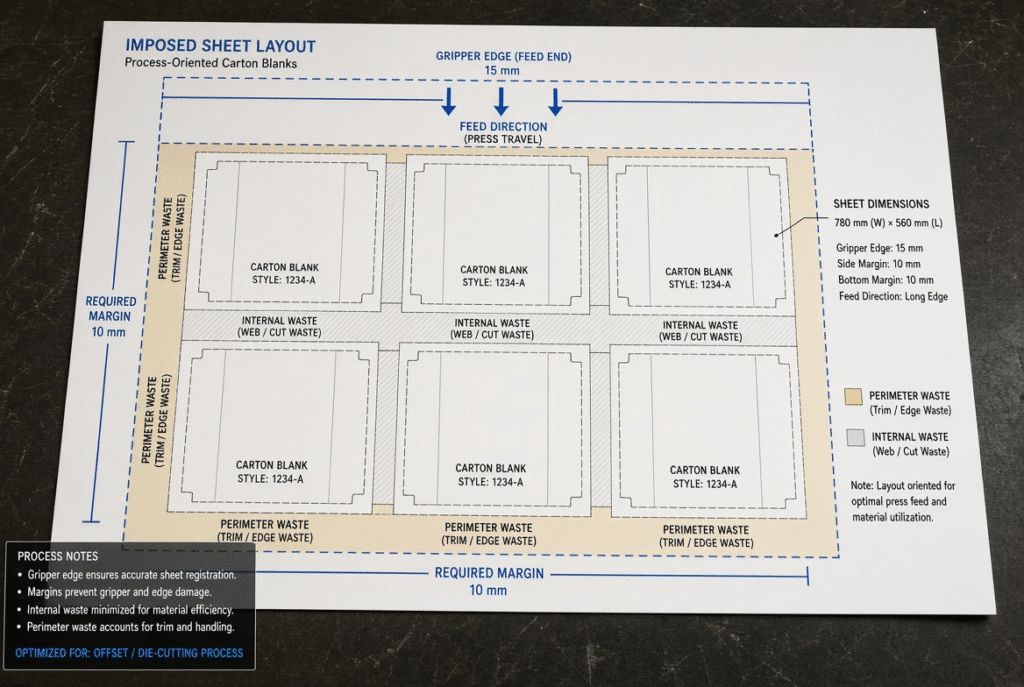
Automatic waste stripping depends on controlled sheet transport. The gripper margin and feed direction therefore belong in the layout discussion. The gripper edge is not ordinary perimeter waste; it is part of the sheet-control system that pulls the blank through die cutting, stripping, and delivery. Usable sheet area, maximum die-cutting area, and stripping-friendly layout area are not always identical.
Keep Critical Carton Features Away from the Gripper-Control Area
Features placed too close to the gripper margin can create problems for sheet control, die cutting, stripping tools, and leading-edge support. Important carton edges, windows, tabs, and print-sensitive areas should be checked against the machine’s required gripper margin and first-cutting-line requirements. The exact margin varies with machine type, sheet size, material, feed system, and confirmed configuration.
Feed Direction Changes the Stripping Strategy
Rotating or changing feed direction alters which carton features sit near the gripper edge and how the sheet is supported. It also changes the behavior of perimeter waste, internal waste, and retained sheet sections. A long narrow window may run more stably in one orientation than another, depending on waste support and tool access. The preferred direction should be confirmed with the die maker and machine supplier.
Plan Gripper Waste Separately from Main Perimeter Waste
The gripper-edge area often needs its own waste-management plan, distinct from the outer skeleton around the carton blanks. Depending on the machine, gripper-related material may be retained until a later stage, removed by a dedicated device, or handled according to the confirmed stripping configuration.
Carton Spacing, Imposition Density, and Stripping Tool Access
Placing more cartons on a sheet improves material utilization, yet extreme density can shrink the space needed for waste channels, stripping pins, support elements, tool clearance, and sheet stability. The most economical layout is not always the one that packs the maximum number of blanks.
More Cartons per Sheet Can Reduce Waste-Control Space
Close spacing creates narrow waste strips and limited room for tooling. Perimeter waste may become weak, internal waste difficult to reach, and stripping pins may lack clearance from finished edges. A tighter layout can save board but may require lower speed, more manual cleanup, more complex tooling, or a different stripping approach. Material yield and operating reliability must be weighed together.
Tooling Access Around Carton Edges and Internal Features
Upper and lower stripping tools need access to selected waste areas. Carton spacing, panel geometry, bridge placement, and proximity to creases determine whether pins, rules, support blocks, and clearance openings can be positioned without interference. Sharing the imposed layout early with the die maker and machine supplier makes spacing adjustments far easier than changing finished dies and stripping boards.
Plan for Delivery, Blanking, and Downstream Handling
Imposition also affects what happens after stripping. A layout that produces a stable sheet may suit later blanking; another may favor connected-sheet handling or manual separation. The required output condition should influence spacing, retained connections, and waste-removal planning. Stripping and blanking remain separate functions; a layout optimized for waste removal still needs review to ensure finished blanks can be separated and stacked as required.
Common Carton Layout Mistakes That Cause Stripping Problems
Many automatic stripping problems originate in layout decisions made before production. The following table links common layout issues to typical plant-floor symptoms and the points that should be reviewed. It is a starting checklist, not a set of universal rules.
Troubleshooting Table: Layout Issue, Production Symptom, and Review Point
| Layout Issue | Likely Production Symptom | What to Review |
| Small internal waste area with limited access | Waste remains in holes or needs manual clearing | Hole geometry, pin access, bridge design, board properties |
| Cartons placed too close together | Weak perimeter waste or tool interference | Carton spacing, waste channels, stripping-tool clearance |
| Critical feature near gripper margin | Leading-edge instability or carton damage | Feed direction, gripper requirement, first cutting line |
| Poorly planned bridges/nicks | Waste tears early or does not release | Bridge location, die-cut quality, stripping path |
| Irregular waste shape without clear exit route | Waste twists, fragments, or enters delivery | Tool contact, lower clearance, waste-removal direction |
| Layout optimized only for material yield | Lower production stability or more manual work | Total cost, setup complexity, speed, scrap, labor |
Difficult jobs should always be evaluated with the actual carton drawing and material sample.
When to Revise the Layout Instead of Adjusting the Machine
Repeated stripping problems should not automatically be solved by changing machine settings or adding more pins. When the layout itself creates unsupported waste islands, insufficient clearance, weak perimeter waste, or gripper-edge conflicts, a layout revision is often the more effective solution. Modest changes in hole shape, carton spacing, bridge location, feed orientation, or waste path can improve manufacturability without altering the visual function of the carton.
How to Review Carton Layouts Before Production or Machine Selection
It is important to have a design-for-manufacturability review before finalizing challenging carton designs, ordering cutting dies, creating stripping tools or quoting an automatic die-cutting machine. The information below can assist a technical team in determining early the feasibility of stripping.
Information to Prepare for a Stripping-Focused Layout Review
- Holes, windows, slots, tabs and complicated cut-outs on the inside.
- All waste including perimeter waste, internal waste, bridges, nicks and retained sheet connections.
- Feed direction and required gripper-margin
- The desired result once the strip is removed.
- The decision on whether carton blanks should stay connected, blanked or simply folded and glued is determined by the market and specific product requirements.
- Forecasted production level, re-run rate and intended environment of use
- Any problems experienced in the current die-cutting, stripping, delivery or manual cleanup.
- Material samples, carton samples, photos or videos (where available)
This package helps you pinpoint layout issues before it’s too late to alter tooling and machine configurations.
Questions to Ask a Die Maker, Tooling Supplier, or Machine Manufacturer
- What areas are likely to be tough to strip automatically?
- Are there sufficient upper and lower stripping tools clearance?
- What is the best way to plan for bridges and nicks in this material and waste structure?
- Is the gripper margin and feed direction appropriate for the machine configuration?
- Should the shape of any hole, spacing of any carton or waste channel be changed prior to the production of the tooling?
- Should full stripping, semi-stripping or another workflow be more appropriate for the job?
- Is the supplier able to test the actual material/carton layout?
- What are the output conditions that the machine is able to reliably produce for this application?
Request application-specific feedback. The maximum-size and maximum speed should not be the only criteria used to determine the carton layout and material for a machine supplier.
Summary Guidance – Design the Waste Path Before the Machine Runs
The carton layout design has an impact on all phases of automatic waste stripping: waste stability, tooling access, bridge behavior, gripper-edge support, sheet transport, waste exit, delivery condition, and downstream handling. The most productive layout is not the one which accommodates the largest number of blanks on a sheet, but the one for which it is possible to die cut, strip, deliver and finish reliably with equipment and manpower available.
Submit your carton dieline, imposed sheet layout and materials information for an automated waste stripping review. If packaging plants are considering integrated die cutting and waste stripping, they can consider discussing the D1060SQ Automatic Flatbed Die Cutting Machine with Stripping with the DAIS technical team and the carton layout and production plan.