
Get a Quote
D1500 | Semi-Automatic Platen Die Cutting

D1500 Semi-Automatic Die Cutting Machine

Designed for large-format paperboard and corrugated packaging applications, the D1500 combines operator-assisted sheet feeding, accurate front and side registration, 400-ton platen pressure, and automatic sheet delivery in one production system.

Its 1500 × 1100 mm maximum sheet capacity supports folding cartons, corrugated packaging, display components, and other large-format die-cutting and creasing applications.

1500 × 1100 mm Maximum Sheet Size
400 t Maximum Working Pressure
5,500 sheets/hour Maximum Working Speed
≤9 mm Corrugated Board Thickness

Actual production speed depends on sheet material, board condition, die layout, operating method, and production environment.

Application Fit

Large-Format Capacity for Operator-Assisted Production

The D1500 is designed for packaging converters that process large sheets and use an operator-assisted feeding workflow. It provides controlled sheet registration before each sheet enters the gripper transport and platen die-cutting process.

This configuration is suitable for plants that require large-format capacity, stable pressure, and automatic paper collection without adopting a fully automated feeding line.

01

Folding Cartons

Die cutting and creasing for large paperboard cartons used in consumer goods, appliances, food packaging, and general retail applications.

02

Corrugated Shipping Cartons

Processing of corrugated board for transport cartons, protective packaging, shipping cases, and industrial packaging components.

03

Retail and Display Packaging

Accurate alignment between printed graphics and cutting lines for display panels, promotional packaging, and retail-ready structures.

04

Heavy Paperboard Products

Flat die cutting and creasing for thick paperboard components that require controlled registration and stable platen pressure.

Best Suited For

  • Packaging plants processing large-format sheets
  • Operations that use operator-assisted sheet feeding
  • Paperboard and corrugated packaging production
  • Jobs requiring die cutting and creasing in one platen process
  • Printed packaging requiring controlled front and side registration
Technical Data

Technical Parameters for Production and Site Planning

The following specifications provide the working basis for evaluating the D1500. Electrical supply, compressed-air requirements, optional equipment, and final component brands must be confirmed in the technical agreement before production.

D1500 technical specifications
Specification D1500
Die-Cutting Type Flat platen
Maximum Sheet Size 1500 × 1100 mm
Minimum Sheet Size 550 × 500 mm
Maximum Die-Cutting Size 1490 × 1090 mm
Minimum Gripper Margin 8 mm
Maximum Working Pressure 400 t
Applicable Paperboard White paperboard ≥250 g/m²
Maximum Corrugated Board Thickness ≤9 mm
Die-Cutting Accuracy ±0.25 mm
Maximum Working Speed 5,500 sheets/hour
Maximum Feeding Pile Height 1,500 mm
Maximum Delivery Pile Height 1,350 mm
Main Motor Power 15 kW
Rated Power 17.3 kW
Machine Weight Approximately 16 t
Overall Dimensions 6560 × 4580 × 2334 mm

Final performance depends on the processed material, sheet flatness, die condition, production setup, and operating environment.

Feeding and Registration

Controlled Sheet Entry Before Every Die-Cutting Cycle

The D1500 uses an operator-assisted feeding process supported by front and side registration mechanisms. Before entering the die-cutting section, each sheet is positioned according to the required print-to-cut relationship.

Sheet-arrival detection helps confirm that the board has reached the correct feeding position. Left and right push-pull side gauges accommodate different registration directions, while the sheet-pressing mechanism helps maintain stable contact during alignment.

01

Operator-Assisted Sheet Entry

The operator controls sheet presentation before the board enters the registration and gripper-transfer process.

02

Sheet-Arrival Detection

The detection system confirms sheet arrival before the machine proceeds with the next operating step.

03

Front Registration

The front gauge establishes the forward position of the sheet for consistent die alignment.

04

Left and Right Side Gauges

Push-pull side gauges allow registration from either side according to the printed sheet and production setup.

05

Stable Sheet Pressing

The sheet-pressing structure applies controlled force to support reliable positioning before transfer.

Die-Cutting Unit

Rigid Mechanical Support for Large-Format Die Cutting

The D1500 die-cutting unit is built around a flat platen structure capable of delivering up to 400 tons of working pressure. The pressure-bearing sections use QT600-3 ductile iron to provide the rigidity required for repeated industrial operation.

A crankshaft and connecting-rod mechanism transfers power through the die-cutting cycle. The worm gear, worm, transmission components, and intermittent mechanism work together to coordinate platen movement and sheet transport.

01

Stable Pressure-Bearing Structure

The rigid body, upper platform, and lower platform support pressure distribution across the working area.

02

Pneumatic Plate Locking

The pneumatic locking device helps secure the die-cutting plate and reduces manual effort during production preparation.

03

Plate-Frame Positioning

The positioning and fine-adjustment structure supports alignment of the cutting die within the working area.

04

Coordinated Mechanical Transmission

The crankshaft, connecting rod, worm gear, chains, and intermittent mechanism coordinate the movement required for each cycle.

05

Lubrication and Oil Cooling

The lubrication system supplies oil to critical transmission areas, while the cooling arrangement helps manage oil temperature during operation.

Platen Die-Cutting Unit
Main Mechanical Drive
Control and Protection

Centralized Monitoring for More Controlled Operation

The D1500 uses a PLC-based control system and operator interface to centralize machine commands and operating information. The interface provides visibility into machine status, production speed, processed-sheet count, and operating conditions.

Limit switches, transmission protection, lubrication monitoring, and safety-related control components work together to support controlled machine operation.

01

Operator Interface

Operating commands and machine information are organized through a centralized control interface.

02

Status and Production Display

The system can display production speed, processed-sheet quantity, accumulated operating data, and machine status.

03

Position and Limit Monitoring

Control components monitor key movement positions and operating limits during the production cycle.

04

Torque Protection

The torque-limiting system helps protect transmission components if abnormal resistance occurs.

05

Lubrication Monitoring

Oil-supply monitoring supports the protection of critical rotating and transmission components.

06

Safety Control

Safety switches and protective devices help reduce operating risk around moving machine sections.

Automatic Delivery

Organized Sheet Collection After Die Cutting

After die cutting, processed sheets enter the delivery section for leveling and pile formation. The paper-collection system combines sheet guidance, air assistance, photoelectric monitoring, and automatic lifting to support orderly delivery.

The system is designed to accommodate different paperboard thicknesses while allowing operators to observe the condition of the completed sheets.

01

Automatic Sheet Leveling

The delivery structure guides processed sheets into position as the pile is formed.

02

Two-Way Air Assistance

Airflow supports sheet separation and alignment during delivery.

03

Photoelectric Pile Monitoring

Photoelectric detection monitors the receiving condition and supports pile-height control.

04

Automatic Delivery-Table Lifting

The receiving table adjusts as the pile height changes during production.

05

Anti-Return Protection

The anti-return structure helps prevent sheets from moving in the wrong direction during collection.

06

Production Sampling

The delivery area allows operators to inspect die-cutting results during production according to the operating procedure.

Procurement Scope

Main Machine Configuration

The D1500 includes the principal mechanical, electrical, pneumatic, transport, and lubrication components required for operation. Exact brands and component models are confirmed in the final technical agreement.

D1500 main machine configuration
System Main Configuration
Main Structure QT600-3 ductile-iron machine body and pressure-bearing structure
Die-Cutting Drive Crankshaft, connecting rod, worm gear and worm
Motion Control Intermittent mechanism and transmission chains
Clutch System Pneumatic clutch
Control System PLC and operator interface
Drive Components Main motor, feeding and delivery motors, servo motor
Monitoring Encoder, photoelectric detection and limit switches
Transmission Protection Torque limiter and protective devices
Pneumatic System Pneumatic components and plate-locking system
Vacuum System Vacuum pump
Lubrication Automatic lubrication pump
Cooling Cooling fan and oil-cooling arrangement
Bearings Industrial-grade bearings according to the final configuration

Component brands and specifications may be updated with equivalent-grade or higher-grade alternatives according to the final technical agreement.

Standard Scope of Supply

D1500 standard scope of supply
Item Quantity Supply Condition
Complete D1500 Machine 1 set Main machine
Die-Cutting Steel Plate 1 Installed on the machine
Die-Cutting Frame 2 One installed and one packed separately
Spare Gripper Bar 1 Supplied with accessories
Gripper Pads 10 Supplied with accessories
Manual Waste-Cleaning Unit 1 Standard supply
Labeling Unit 1 Installed on the machine
Toolbox 1 Supplied with accessories

The signed technical agreement and packing list determine the final scope of supply.

Site Planning

Prepare the Workshop Before the Machine Arrives

The D1500 has overall dimensions of 6560 × 4580 × 2334 mm and an approximate machine weight of 16 tons. The workshop layout must provide more space than the physical machine footprint alone.

Additional clearance is required for operator movement, sheet feeding, finished-pile removal, die-frame handling, maintenance access, electrical cabinets, and installation work.

01

Foundation and Floor

Confirm that the installation area is level and capable of supporting the machine and operating loads.

02

Operating Clearance

Allow sufficient space around the feeding, die-cutting, control, and delivery sections.

03

Material Movement

Plan clear routes for incoming sheets, finished piles, pallets, and material-handling equipment.

04

Electrical Supply

Confirm the required voltage, frequency, phase, cable routing, and protective devices before shipment.

05

Compressed Air

Reserve the required compressed-air connection according to the final technical specification.

06

Unloading and Positioning

Confirm lifting equipment, door dimensions, workshop access, and machine-moving arrangements before delivery.

The final installation drawing should be reviewed by both the buyer and DAIS before the foundation and utility work is completed.

Manufacturing Experience

Built by an Industrial Machinery Manufacturer Established in 1993

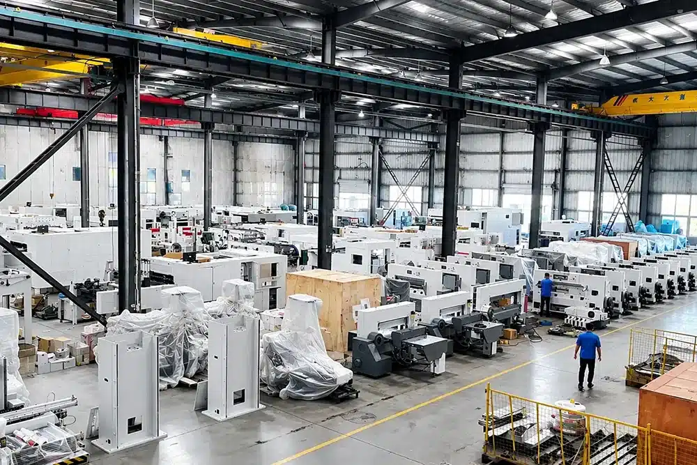
Zhejiang Dais Printing Machinery Co., Ltd. has manufactured printing and post-press equipment since 1993. Its production base in Lishui Economic Development Zone, Zhejiang, China, covers approximately 50,000 square meters.

More than 100 sets of CNC and machining equipment support the production of machine frames, platforms, transmission components, and other critical assemblies.

1993 Established
50,000 m² Manufacturing Base
100+ CNC and Machining Units
50+ Export Countries and Regions
01

Precision Machining

Five-face gantry machining centers and high-precision vertical machining centers support dimensional control of large structural components.

02

Controlled Component Preparation

Robotic plasma cutting and CNC processing improve consistency before machining and assembly.

03

Assembly and Alignment

Major mechanical sections are assembled and aligned according to the machine configuration and production requirements.

04

Pre-Shipment Inspection

The machine is checked before dispatch to verify its configuration, movement, control functions, and general operating condition.

05

Engineering Development

DAIS holds multiple national patents covering technologies associated with paper feeding, machine safety, sheet handling, and printing and post-press equipment.

DAIS machinery is supplied to customers in more than 50 countries and regions.

Worldwide Delivery

Shipment Planning for a 16-Ton Industrial Machine

International delivery of the D1500 requires coordination between machine preparation, accessory packing, loading arrangements, transport documentation, and the receiving conditions at the buyer’s facility.

DAIS reviews the shipment requirements before dispatch so the main machine, separately packed die frame, tools, and supplied accessories can be identified and secured according to the agreed transport method.

01

Pre-Shipment Verification

Check the completed machine against the confirmed technical configuration and scope of supply.

02

Protective Packing

Protect the machine and separately packed accessories according to the agreed shipping method and destination conditions.

03

Loading Coordination

Prepare the loading arrangement according to machine dimensions, weight, transport limitations, and handling requirements.

04

Shipping Documentation

Organize the packing list and relevant shipment documents for delivery and destination handling.

Buyer Information Required

  • Destination country and port
  • Final factory address
  • Site-access limitations
  • Available unloading and lifting equipment
  • Requested delivery schedule
  • Local documentation requirements

Final transport arrangements are confirmed according to the destination and contracted delivery terms.

After-Sales Support

Support from Installation Through Long-Term Operation

The standard warranty period is 12 months from completion of installation and commissioning, provided that the machine is operated and maintained correctly and the applicable contract conditions are followed.

Qualifying parts damaged by non-human factors during the warranty period may be replaced according to the agreed warranty terms. Consumable parts, irregular operation, improper maintenance, unauthorized modification, and operator misuse are excluded unless otherwise stated in the contract.

01

Installation and Commissioning

Installation responsibilities, commissioning arrangements, and engineer attendance are confirmed before shipment.

02

Operator Handover

Machine operation, routine inspection, lubrication, adjustment, and safety requirements should be reviewed during commissioning.

03

Warranty Support

DAIS evaluates reported problems according to the machine condition, operating records, and warranty terms.

04

Spare Parts

Replacement parts remain available after the warranty period and can be supplied according to the confirmed model and component specification.

05

Long-Term Maintenance

DAIS provides continued maintenance and technical support beyond the initial warranty period.

For overseas projects, engineer travel, accommodation, local transportation, and related service expenses are handled according to the sales contract.

D1500 FAQ

Frequently Asked Questions

What materials can the D1500 process?

The D1500 is designed for white paperboard of at least 250 g/m² and corrugated board up to 9 mm thick. Material suitability should be confirmed using the actual board and die-cutting requirements.

What is the maximum sheet size?

The maximum sheet size is 1500 × 1100 mm. The maximum die-cutting area is 1490 × 1090 mm, while the minimum sheet size is 550 × 500 mm.

How does the semi-automatic feeding process work?

An operator presents the sheet to the feeding and registration area. Front and side gauges position the sheet before the gripper system transports it through the die-cutting cycle.

What is the maximum production speed?

The specified maximum working speed is 5,500 sheets per hour. Actual output depends on material condition, sheet size, die layout, operator coordination, and production setup.

What pressure and accuracy does the machine provide?

The D1500 provides a maximum working pressure of 400 tons and a specified die-cutting accuracy of ±0.25 mm under appropriate production conditions.

How much installation space is required?

The machine dimensions are 6560 × 4580 × 2334 mm, but the installation area must also include space for feeding, delivery, maintenance, die changes, operator access, and material handling.

What is included with the standard machine?

The standard supply includes the complete machine, one installed steel plate, two die-cutting frames, one spare gripper bar, ten gripper pads, one manual waste-cleaning unit, one labeling unit, and one toolbox. The signed packing list determines the final supply.

What warranty and overseas service are available?

The standard warranty period is 12 months from installation and commissioning under correct operating and maintenance conditions. Overseas engineer arrangements and related expenses are confirmed in the sales contract.

Application Review

Discuss Your D1500 Die-Cutting Requirements

Send DAIS your material, sheet dimensions, board thickness, required production speed, electrical standard, delivery destination, and installation conditions.

Our team will review the application and prepare a technical proposal based on your production requirements.

Request a D1500 Technical Proposal
Scroll to Top