
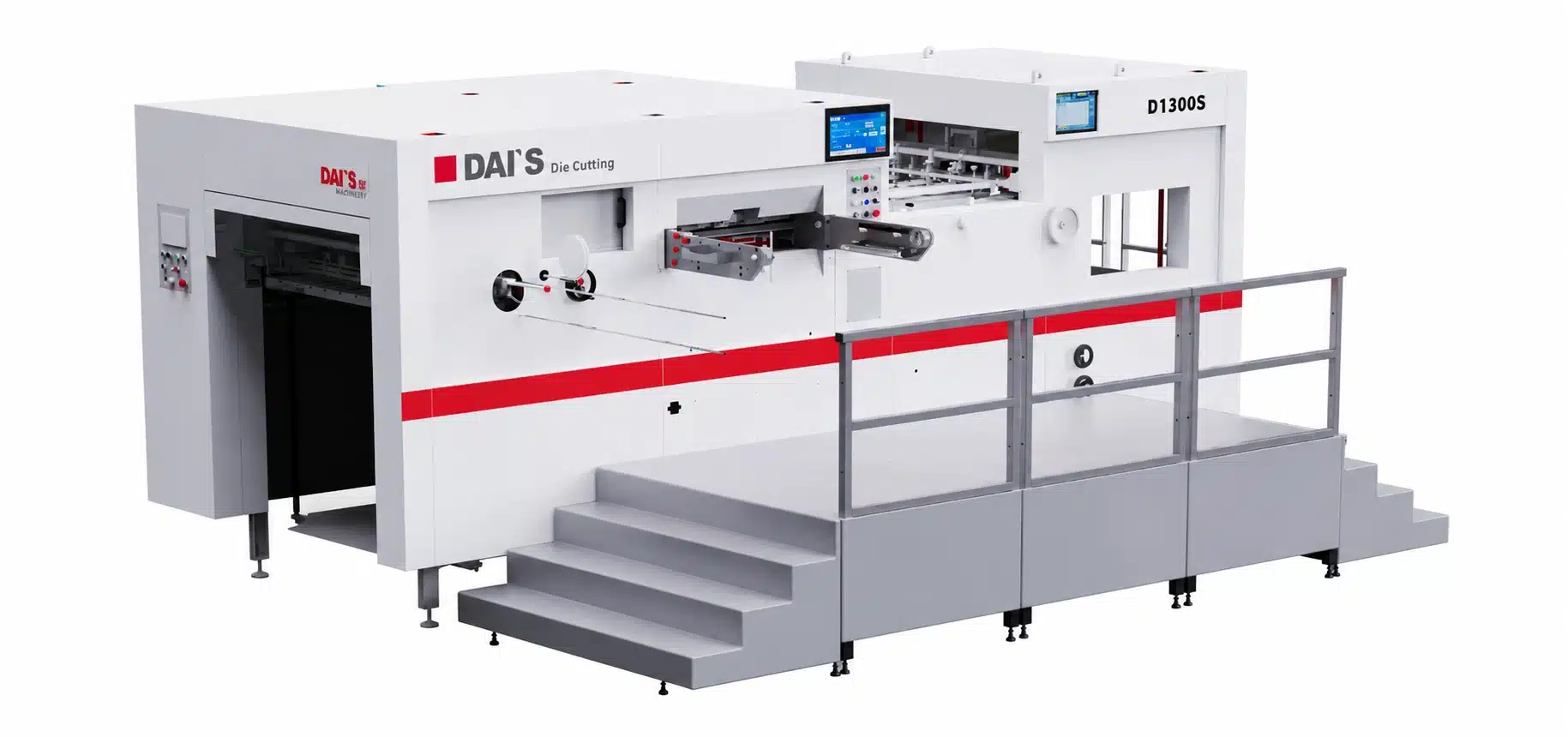
D1300S Fully Automatic Flatbed Die Cutting Machine
Built for large-format paperboard and corrugated packaging, the D1300S integrates automatic high-pile feeding, precise sheet registration, high-pressure flatbed die cutting, and high-pile delivery into one production platform. It processes sheets up to 1,300 × 950 mm and is designed to help packaging converters achieve stable, repeatable production across a wide range of board conditions.
- Maximum Sheet Size:
- 1,300 × 950 mm
- Maximum Cutting Size:
- 1,290 × 920 mm
- Maximum Speed:
- 6,500 sheets/hour
- Maximum Cutting Pressure:
- 350 t
- Exported to 50+ Countries and Regions
- Export Packing and Shipping Support
- Overseas Installation and Training Available
Large-Format Die Cutting for Paperboard and Corrugated Packaging
The D1300S is a fully automatic flatbed die cutting machine developed for packaging manufacturers that process large paperboard and corrugated sheets. It brings sheet feeding, registration, die cutting and creasing, and high-pile delivery together in a continuous production workflow, reducing the manual handling normally required between these operations.
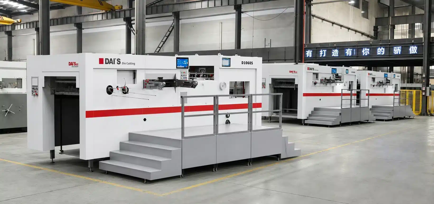
With a maximum sheet size of 1,300 × 950 mm and a maximum cutting area of 1,290 × 920 mm, the machine provides the working area needed for large packaging layouts and multi-up production. Its adjustable feeder, sheet-positioning system, rigid die-cutting structure, and controlled delivery section are designed to maintain stable sheet movement from the feeding pile to the finished stack.
Suitable Materials
The documented working range includes:
- Paperboard from 100 g/m²
- Corrugated board up to 8 mm thick
- Greyboard and similar rigid sheet materials, subject to sample evaluation
Actual performance depends on the material grade, flute profile, sheet flatness, surface finish, die layout, and production speed. For unfamiliar or difficult substrates, DAIS recommends reviewing the material specification and testing representative samples before the final machine configuration is confirmed.
Typical Packaging Applications
The D1300S can be evaluated for applications such as:
- Folding cartons and paperboard packaging
- Corrugated shipping and retail packaging
- Litho-laminated corrugated sheets
- Display and point-of-sale packaging
- Large-format box blanks
- Protective packaging inserts and partitions
- Other die-cut and creased paper-based packaging components
Who the D1300S Is Designed For
This model is intended for converters that need a larger working format, automatic sheet handling, and consistent die-cutting pressure for mixed paperboard and corrugated production. The final recommendation should be based on the customer’s sheet range, board condition, die layout, required output, available factory space, and downstream waste-removal process.
From Automatic Feeding to Controlled High-Pile Delivery
The D1300S is organized around five connected systems: high-pile feeding, sheet conveying and registration, flatbed die cutting, electrical control and safety monitoring, and high-pile delivery. Each system performs a distinct role in keeping large sheets moving accurately and consistently through the machine.
Automatic High-Pile Feeding System
The feeder is designed to work with paperboard, corrugated board, and greyboard in different sheet conditions. Servo-controlled adjustment allows the operator to adapt the suction position, angle, and height to suit the material and compensate for sheet deformation. This is particularly useful when handling large sheets that may not remain perfectly flat throughout the pile.
Main and auxiliary feeding arrangements support continuous production, while the feeding table can be fine-tuned during operation. Sheet-following protection and feeder collision detection help reduce the risk of operating errors. A shingled sheet-feeding pattern supports stable transfer from the pile into the conveying section.

Key feeder functions include
- Servo-controlled feeder adjustment
- Adjustable suction angle and height
- Main and auxiliary feeding changeover
- Feeder collision detection
- Sheet-following and anti-misoperation protection
- Fine adjustment of the feeding table during operation
- High feeding pile of up to 1,550 mm
- Optional pre-loading arrangement according to the final configuration
Stable Sheet Conveying and Precise Registration
After a sheet leaves the feeder, the conveying section controls its speed and guides it toward the registration position. Photoelectric double-sheet detection monitors the incoming material, while adjustable brush wheels and wear-resistant polyurethane transport wheels help maintain stable sheet contact.
Front and side registration systems position each sheet before it enters the die-cutting unit. Left- and right-side push-pull gauges provide flexibility for different printing registration requirements, helping the machine work with printed sheets where the cutting and creasing layout must follow existing graphics.
Key conveying and registration features include
- Controlled sheet-feeding speed
- Photoelectric double-sheet detection
- Industrial sheet-conveying belts
- Wear-resistant polyurethane transport wheels
- Adjustable rubber and brush wheels
- Front registration system
- Left and right push-pull side gauges
- Fine adjustment for printed-sheet alignment
High-Pressure Flatbed Die-Cutting Unit
The die-cutting section is built around a rigid load-bearing structure. High-strength QT600-3 ductile iron is used for key pressure-bearing components to support dimensional stability under repeated production loads. The main drive combines a heavy-duty crankshaft, wear-resistant worm drive, and high-precision intermittent mechanism to coordinate the platen movement and gripper-bar transport.
A pneumatic plate-locking arrangement helps reduce setup time and provides secure positioning of the die-cutting frame. The frame uses an intermediate positioning and fine-adjustment system to support accurate alignment. Automatic lubrication and oil-air cooling help protect the main transmission during extended operation.
Key die-cutting functions include
- Maximum cutting pressure of 350 t
- QT600-3 ductile-iron pressure-bearing structure
- Heavy-duty crankshaft and worm-drive transmission
- High-precision 240-degree intermittent mechanism
- Pneumatic plate locking
- Die-frame positioning and fine adjustment
- Automatic lubrication monitoring
- Oil-air cooling for the drive system
- Maximum documented die-cutting area of 1,290 × 920 mm
Electrical Control, Monitoring and Safety
The control system gives operators centralized access to machine settings, operating status, and production monitoring. The documented configuration includes a 15-inch human-machine interface and a 7-inch auxiliary display. PLC control coordinates the feeder, transport, die-cutting, and delivery sections.
Photoelectric monitoring, safety sensing, torque protection, and lubrication supervision are used to monitor key operating conditions. The machine is designed to stop or alert the operator when specific abnormal conditions are detected, helping protect personnel, sheets, tooling, and drive components.
Key control and safety functions include
- PLC-based machine control
- 15-inch main human-machine interface
- 7-inch auxiliary display
- Real-time production monitoring
- Photoelectric sheet detection
- Infrared safety sensing
- Torque-limiting protection
- Lubrication monitoring and low-oil protection
- Controlled voltage regulation according to the final electrical configuration
High-Pile Delivery and Non-Stop Sampling
The delivery system receives die-cut sheets and organizes them into a controlled pile. Automatic pile lifting, sheet-leveling devices, and two-way air assistance help maintain an orderly stack across both thinner paperboard and thicker corrugated materials.
Photoelectric monitoring tracks the receiving process, while anti-return protection and main-chain protection support stable operation. A non-stop sampling function allows the operator to inspect die-cutting quality during production without stopping the entire machine under normal operating conditions.
Key delivery functions include
- Automatic pile lifting control
- Maximum delivery pile height of 1,250 mm
- Automatic sheet-leveling device
- Two-way air assistance
- Photoelectric delivery monitoring
- Anti-return sheet protection
- Main-chain protective device
- Non-stop production sampling
Plan the Site Before the Machine Arrives
The D1300S is a large industrial machine, so installation planning should begin before production and shipping are completed. The documented machine dimensions are approximately 7,778 × 4,397 × 2,262 mm, excluding the auxiliary table identified in the source document. The final footprint may change with the selected feeder, pre-loading arrangement, delivery system, platforms, and safety guards.
DAIS should provide an approved general-arrangement drawing for the exact ordered configuration. The customer can use this drawing to confirm the foundation, working clearances, electrical connection, compressed-air connection, access route, unloading method, and future maintenance space.
Site-Planning Checklist
Before delivery, confirm the following:
- Final general-arrangement and installation drawings
- Foundation dimensions and load-bearing requirements
- Clear operating space around the feeder, die-cutting unit, and delivery
- Access for die-frame changes, cleaning, inspection, and maintenance
- Factory door, corridor, turning, and overhead-clearance dimensions
- Electrical voltage, frequency, phase, grounding, and connection location
- Compressed-air capacity, pressure, and connection location
- Unloading equipment and lifting capacity for each shipping module
- Safe temporary storage for separately packed accessories
- Environmental conditions suitable for electrical and mechanical equipment
- Availability of customer technicians and operators during installation
Export Packing and Worldwide Shipping
International delivery of a large die-cutting machine requires more than booking ocean freight. The machine must be prepared for moisture, salt air, vibration, lifting, transshipment, and inland handling. DAIS coordinates the packing and shipment plan according to the ordered machine configuration, destination, agreed Incoterms, port requirements, and the customer’s unloading conditions.
The final shipping plan is prepared after the machine configuration has been frozen. It should identify each shipping module, package dimensions, gross and net weight, lifting points, container requirements, separately packed accessories, and the tools or equipment required at the destination.
Export-Ready Packing
Secure Container Loading
Worldwide Ocean Freight Support
Shipping Documentation Support
Delivery-to-Installation Coordination
Export Packing and Corrosion Protection
Before packing, exposed metal surfaces and vulnerable machine areas should be prepared for export transportation. Electrical components, control equipment, loose accessories, and precision parts require protection from moisture and impact. Packages should be clearly numbered so the customer can compare them with the packing list during unloading and unpacking.
The project-specific packing plan may include:
- Cleaning and pre-shipment inspection
- Corrosion protection for exposed metal surfaces
- Moisture-resistant wrapping and desiccant protection
- Separate protection for electrical and precision components
- Export-ready cases for loose accessories where required
- Package identification matched to the packing list
- Packing and loading photographs for shipment records
Container Loading and Cargo Securing
The D1300S may need to be divided into shipping modules according to its final configuration and the selected transportation method. Heavy sections must be blocked, braced, and secured to reduce movement during inland transport, port handling, and ocean transit. Accessories and removable components should be packed so they cannot damage the main machine or become lost during handling.
The exact container type, number of containers, package dimensions, and loading sequence must be confirmed from the final packing plan. These details should not be estimated from the assembled machine dimensions alone.
Ocean Freight and Inland Transportation
Ocean freight is the normal international transport method for a machine of this size and weight. Inland trucking or other regional transport can be coordinated according to the origin, destination port, final factory location, and agreed scope of service. Available Incoterms—such as FOB, CFR, or CIF—should be confirmed in the commercial quotation and contract.
Air freight should be considered primarily for urgent spare parts or small components, not as the standard transport method for the complete D1300S.
Shipping and Customs Documents
The required document package depends on the contract and destination country. It may include:
- Commercial invoice
- Packing list
- Bill of lading
- Certificate of origin when required
- Machine manuals and electrical documentation
- General-arrangement and installation drawings
- Contracted compliance or inspection documents
The importer remains responsible for confirming local customs, tax, inspection, electrical, safety, and machinery-import requirements before shipment unless the contract assigns specific responsibilities differently.
Arrival and Installation Coordination
Before the vessel arrives, the customer should confirm customs arrangements, inland delivery, factory access, lifting equipment, unloading personnel, temporary storage, and the installation schedule. DAIS can coordinate technical information for unloading and installation preparation according to the final service agreement.
Plan the Shipment Before Dispatch
Confirm the final packing method, shipping modules, container requirements, destination information, and unloading conditions before the machine leaves the factory.
Built by an Experienced Printing Machinery Manufacturer
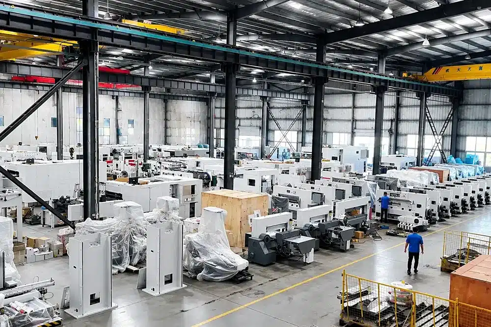
Zhejiang Dais Printing Machinery Co., Ltd. was established in 1993 and operates from a 50,000-square-meter manufacturing site in Lishui Economic Development Zone, Zhejiang Province, China. The company designs and manufactures printing and post-press equipment for customers in more than 50 countries and regions.
Company Established
Manufacturing Site
CNC and Metal-Processing Equipment
Countries and Regions
Controlled Component Processing
DAIS supports its machinery production with more than 100 sets of CNC and metal-processing equipment, including five-face gantry machining centers, high-precision vertical machining centers, and robotic plasma-cutting systems. This manufacturing capacity allows key structural and transmission-related components to be processed with controlled geometry before assembly.
Manufacturing Quality and Stability
For a high-pressure flatbed die cutter, the accuracy of the frame, wallboards, platen-related structures, transmission installation, and sheet-handling alignment affects long-term production stability. The D1300S therefore depends not only on purchased electrical components, but also on machining quality, assembly control, commissioning, and the final technical configuration.
Relevant Patented Engineering
DAIS holds national patents covering die-cutting, paper feeding, paper lifting, hydraulic safety, and related machinery mechanisms. Selected patents relevant to die-cutting and sheet-handling technology include:
| Patent | Patent Number |
|---|---|
| Feeding Unit of a Die-Cutting Machine | ZL201820328715.3 |
| Supporting Rotating Disc of a Die-Cutting Machine | ZL201820328948.3 |
| Pumping Plate Bracket Device of a Die-Cutting Machine | ZL201820328769.X |
| Safety Switch | ZL201720068618.0 |
Patent ownership demonstrates development activity at the company level. The applicability of any individual patent to a specific D1300S configuration should be confirmed before making a model-specific legal or performance claim.
What Customers Can Request Before Shipment
Depending on the order and agreed inspection process, customers may request configuration confirmation, machine photographs, test-run records, packing information, and other acceptance documentation specified in the contract.
Support from Installation to Long-Term Operation
The value of a large die-cutting machine depends on correct installation, operator training, preventive maintenance, and access to technical support after production begins. DAIS provides support according to the machine contract, destination, service scope, and local conditions.
Installation and Commissioning
Installation support can include review of site preparation, assembly guidance, leveling, electrical and pneumatic checks, startup, operating checks, and production commissioning. Overseas on-site service is available subject to the final service agreement. Engineer travel, visa, accommodation, local transportation, service charges, and customer responsibilities must be defined in the contract before dispatch.
Operator and Maintenance Training
Training should cover:
- Safe startup and shutdown
- Feeder and registration adjustment
- Die-frame installation and positioning
- Pressure and sheet-handling setup
- Delivery adjustment
- Lubrication and routine inspection
- Cleaning and preventive maintenance
- Alarm response and basic troubleshooting
- Procedures for changing materials and production jobs
The customer should assign appropriate operators, electricians, and maintenance technicians to participate in commissioning and training.
Warranty
The source service document specifies a 12-month warranty beginning after installation and commissioning, provided that the machine is correctly operated and maintained. Final warranty start date, covered components, labor, spare-part freight, engineer costs, consumables, exclusions, and claim procedures must follow the signed sales contract.
Damage caused by misuse, unauthorized modification, improper maintenance, unsuitable operating conditions, normal wear, or consumable-part use is generally outside standard warranty coverage unless the contract states otherwise.
Spare Parts and Long-Term Support
DAIS can continue supplying technical assistance and spare parts after the warranty period. Parts outside warranty can be quoted according to the required item, current availability, production status, and shipping destination. Customers should provide the machine serial number, component photographs, nameplate information, fault description, and operating records when requesting support.
Plan Installation and Service Before Shipment
Confirm the installation method, training scope, customer responsibilities, engineer arrangements and after-sales terms before the machine is dispatched.
Discuss Your D1300S Application
Every die-cutting project begins with the material, sheet format, product layout, and production target. Send DAIS your application information so the technical team can evaluate whether the D1300S is suitable and prepare an appropriate configuration, quotation, installation plan, and shipping proposal.
Please Include
- Material type
- Paperboard basis weight or board thickness
- Corrugated flute type and total thickness
- Minimum and maximum sheet sizes
- Product drawings, photographs, or physical samples
- Required die-cutting, creasing, perforating, or waste-removal operations
- Expected production output
- Local voltage and frequency
- Destination country and preferred port
- Required delivery or installation schedule
DAIS will review your application before recommending the final machine configuration.