
Lead Edge Feeding Designed to Reduce Surface Damage
The front feeding section is one of the defining features of the D1060Y.
The feeding structure uses food-grade 304 material together with a pressure-free, scratch-resistant design intended to reduce marking on the sheet surface during feeding.
This is particularly useful when working with printed or laminated surface papers where visible scratches can affect the appearance of the finished packaging.
By controlling the board from the leading edge, the system provides a practical feeding solution for thicker grey board and corrugated materials that can be more difficult to handle with conventional paper-feeding methods.
Feeding System Highlights
Key characteristics of the D1060Y feeding section- Lead edge board feeding
- Food-grade 304 contact material
- Pressure-free feeding design
- Scratch-resistant sheet handling
- Suitable for printed and laminated board surfaces
- Designed for rigid and corrugated sheet materials
Controlled Sheet Transport Before Every Die-Cutting Cycle
Accurate die cutting starts before the sheet reaches the cutting platen.
The D1060Y paper feeding section uses controlled sheet transport, photoelectric detection, adjustable transport wheels and front/side registration mechanisms to guide each sheet into position.
The feeding speed is controlled to reduce unnecessary impact between sheets and support stable delivery into the registration area.
Paper Feed Stand
The paper feed stand incorporates:
- Controlled paper-feeding speed adjustment
- Photoelectric double detection
- Paper conveyor belt system
- Wear-resistant polyurethane transport wheels
- Adjustable rubber wheels
- Adjustable brush wheels
- Controlled sheet positioning before registration
These components work together to guide the material smoothly toward the front and side gauges.
Front & Side Registration
The D1060Y uses front and side positioning mechanisms to align the sheet before it enters the die-cutting section.
Left and right push-pull side gauges are provided to accommodate different registration requirements and help maintain positioning consistency across the production run.
For packaging manufacturers working with pre-printed sheets, reliable registration is particularly important because the die-cutting position must correspond accurately with the printed graphics.
Heavy-Duty Flatbed Die Cutting with Fine Positioning Control
At the center of the D1060Y is a flatbed die-cutting unit capable of producing up to 300 tons of working pressure.
The pressure-bearing structure uses high-strength QT600-3 ductile iron, while the transmission and movement system incorporates heavy-duty mechanical components designed for continuous industrial production.
Die-Cutting System Features
Structural, transmission and positioning technologies used in the D1060Y die-cutting section.QT600-3 Pressure-Bearing Structure
High-strength ductile iron is used in critical pressure-bearing components.
Heavy-Duty Crankshaft Construction
The crankshaft is manufactured from alloy steel and processed for demanding mechanical operation.
Wear-Resistant Worm Gear System
The worm gear and worm system is designed for long-term transmission performance.
240° Intermittent Mechanism
A high-precision intermittent mechanism controls the movement sequence through the die-cutting cycle.
Pneumatic Locking
The pneumatic locking system allows the die-cutting assembly to be secured efficiently during operation.
Fine Plate Positioning
The die-cutting plate frame incorporates an intermediate positioning system with fine adjustment.
Strong Lubrication System
Centralized lubrication supports the main moving and transmission components during continuous production.
Oil-Air Cooling
The machine is equipped with cooling support for operating temperature control.
Maximum standard die-cutting size is 1050 × 760 mm, with a minimum gripper margin of 8 mm.
Electrical Components Selected for Stable Machine Operation
The D1060Y integrates PLC control, photoelectric monitoring, electrical protection and motor control components to coordinate feeding, die cutting and delivery.
The electrical configuration includes components from established industrial suppliers such as Schneider, Omron, NSK and other specified manufacturers.
Operators can monitor machine status through the control interface while sensors and electrical components support coordinated operation throughout the production process.
Control & Electrical Highlights
- PLC-based machine control
- 15-inch operator interface
- Schneider control components
- Meiji photoelectric sensing
- Omron encoder
- Servo-controlled auxiliary movement
- Electrical protection components
- Centralized lubrication control
- Machine-status monitoring
The electrical configuration is designed around practical operation, maintenance access and coordinated control of the machine's major working sections.
Organized Delivery for Continuous Production
After die cutting, the receiving section controls the sheets as they leave the machine and enter the delivery pile.
The system combines sheet leveling, air assistance, photoelectric monitoring and automatic table lifting to help keep the delivered sheets organized.
Automatic Paper Leveling
Supports more uniform stacking as sheets enter the delivery section.
Two-Way Air Assistance
Airflow assists sheet control during delivery.
Photoelectric Delivery Monitoring
Sensors help monitor the sheet receiving process.
Automatic Lifting Table
The delivery table adjusts automatically as the pile height changes.
Anti-Return Device
Helps prevent sheets from moving backward during delivery.
Main Chain Protection
Protective mechanisms are incorporated around the main delivery chain.
Non-Stop Device
The delivery section is equipped with a non-stop operating function.
Maximum paper collecting height is 1500 mm.
Plan the Installation Space Before Machine Delivery
The D1060Y is a large industrial machine with an overall footprint of approximately 6904 × 4047 × 2180 mm and a machine weight of approximately 16 tons.
A dedicated installation drawing is available to show the machine in both elevation and plan view, helping customers review the required installation area before shipment and commissioning.
The installation drawing should be reviewed together with the final machine configuration before the equipment is delivered to the production site.
D1060Y Installation Drawing
Elevation and plan-view engineering information for production-site planning.
Review the final machine configuration and installation drawing before shipment so that floor space, access and commissioning requirements can be prepared in advance.
Worldwide Shipping for D1060Y Die Cutting Machines
DAIS supplies printing and post-press machinery to customers in international markets and supports the shipment of D1060Y die cutting machines to printing and packaging manufacturers worldwide.
Because the D1060Y is a large industrial machine, shipping preparation should be coordinated together with machine configuration, destination and installation requirements.
Export Shipment Planning
Shipment arrangements can be prepared according to the machine dimensions, destination and transport requirements.
Machine & Accessory Preparation
The machine and supplied accessories are prepared for long-distance international transportation before dispatch.
Shipping Documentation
Commercial and shipment documentation can be prepared to support the international delivery process.
Installation Coordination
Machine dimensions and installation information can be reviewed before shipment so that customers can prepare the production site before the equipment arrives.
Planning to Import a D1060Y?
Tell us your destination country and project requirements. Our team can discuss machine configuration, shipment preparation and installation requirements with you before ordering.
Industrial Machinery Manufacturing Since 1993
Zhejiang Dais Printing Machinery Co., Ltd. has specialized in printing and post-press machinery since 1993.
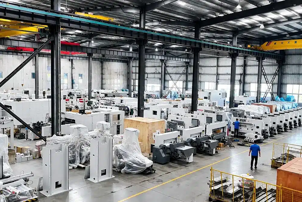
Our manufacturing facility in Zhejiang, China covers approximately 50,000 square meters and is supported by more than 100 sets of CNC and advanced machining equipment, including large machining centers and automated metal-processing systems.
This manufacturing capability allows critical machine structures and mechanical components to be produced and inspected under controlled production conditions.
Established in 1993
Decades of experience in printing and post-press equipment.
Manufacturing Facility
Dedicated production space for industrial machinery manufacturing and assembly.
CNC & Advanced Machines
Machining capability for large and precision mechanical components.
Global Market Experience
DAIS machinery has been supplied to customers in more than 50 countries and regions.
DAIS also holds multiple national patents covering paper handling, safety mechanisms, die-cutting machine structures and related equipment technologies.
Our objective is straightforward: build industrial machinery that customers can operate reliably, maintain practically and use for long-term production.