

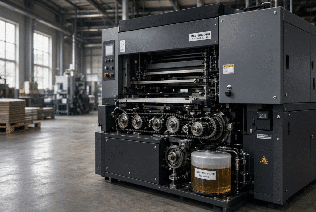
In platen die cutters, a forced lubrication system actively pushes the lubricant to the critical moving parts to ensure that the moving parts such as chains, bearings, gears, crankshafts etc run under controlled friction and heat. It’s not just an oil tank. It is a system of components such as pumps, reservoir, filters, distribution lines and metering points and monitoring functions which must function together. If delivery proves to be insufficient, the machine may be able to keep running until wear or seizure sets in, or until production is halted entirely.
This is usually seen in the factory as an alarm that sounds for low oil or a hot bearing housing or rising chain noise which comes back after a rapid reset. Those signals are troublesome, not minor warnings.
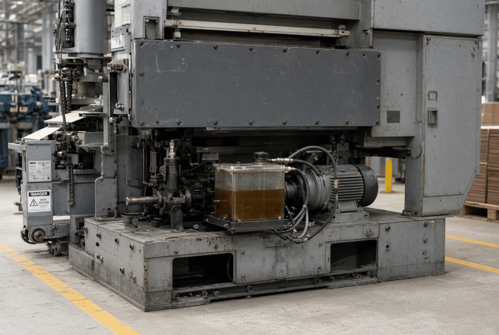
What Is a Forced Lubrication System?
A forced lubrication system supplies lubricant to a machine through a pump to flow through lines or to specific machine parts. Does not depend on gravity, splash and manual application. How it is set up depends on the platen die cutter model used. There are systems that deliver these continuously, others intermittently or based on machine cycles, and a lot of systems that have sensors with level, pressure or flow monitoring. Always use the machine diagram and manual to determine the configuration for your machine.
Forced Lubrication Versus Manual Lubrication
Manual lubrication relies on the operator’s ability to lubricate at the right time, place and in the proper quantity. The access and consistency and timeliness are crucial. Forced systems are used to provide only selected points in their operation or during scheduled cycles, thereby minimizing the need for individual application. Does not eliminate the requirement for reservoir filling, filter inspection, line checks, cleaning or periodic service. There is still a need for discipline to maintain both methods.
Main Components of the System
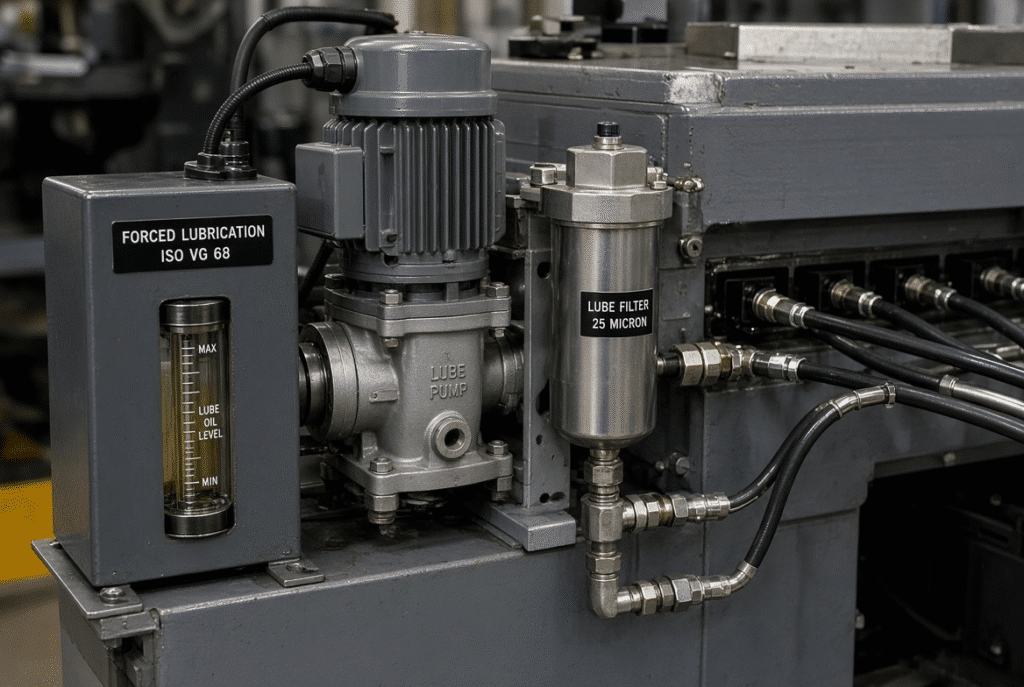
These are usually the parts that make up an oil system: oil reservoir, pump, filter or strainer, distribution manifold, metering points, delivery lines, pressure or flow monitoring devices, oil-level sensor, and an alarm or automatic shutdown function. Not all elements are found on all platen die cutter. Final layout must be verified according to manufacturer’s documentation.
Why Distribution Matters
Having a full reservoir does not indicate that all lubrication points are getting oil. One component may be under-lubricated if the line is blocked, the fitting is damaged, the metering point or pump is failed and the other components appear normal. It is important to look for delivery of not just the quantity, but also the quality.
What Does Forced Lubrication Protect?
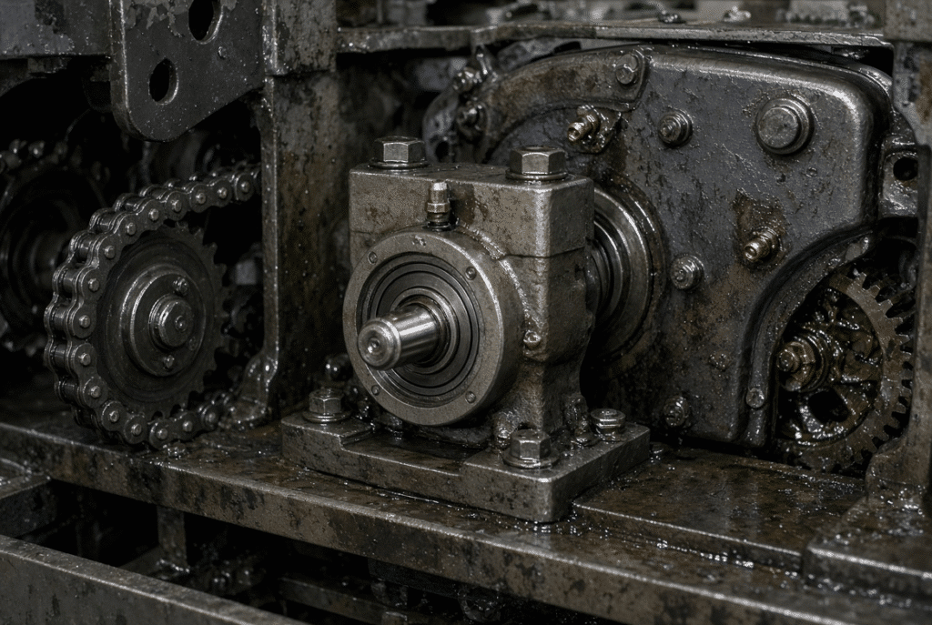
Controlled lubrication minimizes friction, keeps heat generation in check, controls wear, and provides for smooth transmission operation. Poor delivery can increase the potential for seizure, damage to components, sheet transport issues and unexpected downtime. Protected components are different depending on machine design.
Chains, Sprockets and Sheet-Transport Components
Lubrication helps to minimize friction and wear of transport chains and related drive elements. Poor delivery can generate noise, heat, elongation, sheet-transport instability and even uneven movement. These can be a factor in registration drift, slipping of sheets or jams or delivery issues. Lubrication is not the cause of all transport problems.
Bearings and Rotating Supports
Bearings help to support the rotation of shafts and movement of assemblies. Lack of or poor lubricant increases heat, noise, vibration and wear. Guarded or load-bearing bearings must be replaced or inspected by trained personnel and proper energy isolation must be performed.
Gears, Worm Gears and Transmission Components
Sliding and rolling contact under load is controlled by gears and worm gears. The correct viscosity and additive package for the lubricant is a design requirement. Inadequate or incompatible lubricant will cause excessive wear and heat. Do not use any one oil grade for all gearboxes or chain circuits.
Crankshaft and Intermittent Mechanisms
The crankshaft and intermittent mechanism are used to coordinate the motion of high loads or timed motion during the die-cutting cycle. Bad lubrication can impact smooth running, timing stability, vibration and component life. Pressure accuracy and registration are not controlled by lubrication. Mechanical movement must occur in a stable fashion to produce predictable cycles.
Clutches, Couplings and Other Moving Parts
Some components are lubricated by the forced system, while others must be lubricated using other means or are not oil lubricated at all. Never assume that one reservoir is meant to lubricate all the moving parts on the machine.
How a Forced Lubrication System Operates During Production
Lubricant flows from storage through the lubricant pump and distribution system to the areas where lubricant is required, and sensors monitor for unsafe conditions.
Reservoir and Pump Operation
The approved lubricant is stored in the reservoir. Oil is pumped into the distribution system with a pump, typically an electric pump, and microcomputer-controlled on the more modern pumps. Pump activity can be continuous, intermittent or cycle linked. Check the machine manual for the expected operation, don’t assume that the pump will always be audible or visible.
Distribution Lines and Metering Points
Lubricant is directed to specific parts by lines, manifolds and metering points. A line can be connected and blocked with leakage or delivering less than expected. At the time of a scheduled service qualified technicians should check the condition and delivery.
Monitoring, Alarms and Automatic Shutdown
There are many machines that check the oil level, oil pressure, oil flow, and/or pump condition and will alarm or shut the machine down if unsafe conditions are detected. Functions depend on the model. Do not ignore an alarm or reset it over and over again if no cause is known.
Daily Checks for Operators
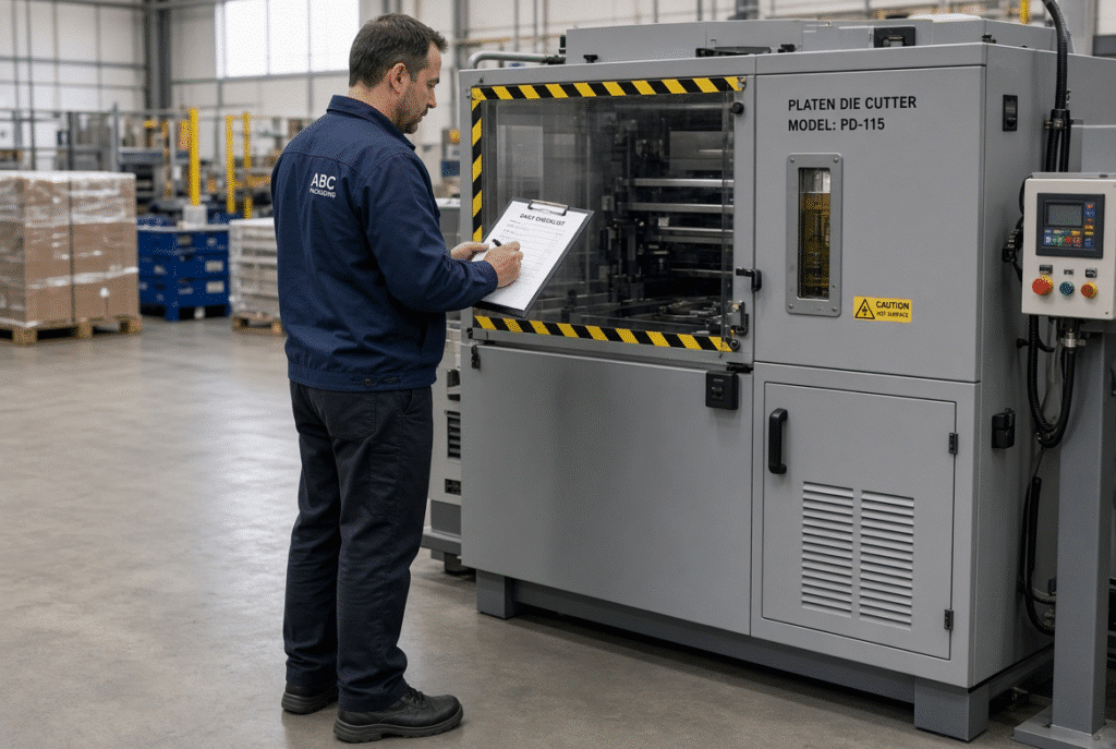
Daily checks are on the obvious condition and machine performance. No systems, whether they are pressurized, electrical or guarded, should be opened by anyone other than an authorized operator.
Check Oil Level and Reservoir Condition
Check oil level indicator or reservoir as per the machine’s service manual. The oil should be clean and at the correct oil level and should have no foreign material or unusual discoloration. NEVER use an unapproved product for topping. Report on low level or abnormal appearance and adhere to approved procedure.
Check for Leaks and Damaged Lines
Check for oil at fittings, hoses, pump connections, reservoir, manifolds or accessible delivery points. A slip hazard occurs when oil is spilled. Never tighten or repair pressurized lines when machine is operating.
Observe Alarms and Machine Behavior
Keep a record of lubrication alarms, pump warnings, unusual noise, heat, vibration, slow moving or repeated stops. Delivery can be compromised without a machine stopping. Stop and investigate as per the safety procedure, don’t ignore the warning.
Keep the Area Clean
Paper dust, board fibers, clean up and spilled oil can cover up leaks and pollute maintenance areas. Cleaning accessible areas allows for easier inspection and reduces risk of contamination. Clean using approved methods and prevent use of lubricant on surfaces in contact with paper.
Weekly and Monthly Maintenance Tasks
Tasks for the week and month extend beyond that of days. Frequency needs to be tailored to machine hours, the dust load for the material, production speed, and manufacturer’s instructions.
Inspect Pump, Filter and Distribution Components
Technicians inspect pump operation, filters, strainers, manifolds, metering points, fittings and delivery lines to ensure that lubricant is delivered to the proper points at the correct rate or pressure. Do not use any other values that are not mentioned in the technical documentation of the machine.
Check for Blocked or Damaged Lines
When reservoir level and pump show normal condition, but the line is partially clogged, wear can occur at the specific area. Symptoms are temperature differences in the components, sounds from a single place, or lubricant not detected at a known location. Line testing is done by qualified persons using approved procedures.
Monitor Lubricant Condition
Be alert to any contamination, discoloration, unusual odors, metal particles, water ingress or excessive viscosity change. The response is based on the machine manual and guidance from the lubricant supplier. Don’t mix oils or use products unless technically approved.
Review Consumption and Refill History
Abnormal operating condition, blocked return path, damaged seal, and leak could all be indicated by unusual oil consumption. Monitor refill dates, amounts, alarms and maintenance activity to make trends apparent.
Inspect Protected Machine Components
Condition checks should be included on chains, bearings, gears, crankshafts and intermittent mechanisms for scheduled maintenance. The purpose is to detect wear prior to secondary damage due to lubrication failure. Never remove a guard or enter into hazardous areas without isolation and authorization.
Lubricant Selection, Contamination and Compatibility
The wrong lubricant can be as bad as using insufficient lubricant. Selection is required to conform to the specification of the machine manufacturer and may vary among reservoirs/circuits.
Follow the Machine-Specific Lubricant Specification
Viscosity, additives, operating temperature, load and component design determine the correct lubricant. A product suitable for one gearbox or chain system may be unsuitable for another. Do not substitute without confirmation from the manual or the manufacturer.
Avoid Mixing Incompatible Lubricants
Topping up with an unknown or incompatible product can alter viscosity, additive performance or seal compatibility. When the lubricant identity is uncertain, consult the manufacturer or a qualified service technician. Label containers and maintain a controlled inventory.
Prevent Dust, Water and Metal Contamination
Paper dust, board fibers, water, cleaning chemicals and metal wear particles can enter the system and accelerate wear. Store lubricant in sealed containers, use clean refill tools, and inspect filters or strainers according to the machine instructions.
Lubricant Level: Too Low and Too High
Low level risks insufficient delivery and pump damage. Overfilling can produce leakage, foaming, heat or contamination. Always use the approved level indicator and fill procedure; never fill “to the top.”
Warning Signs of Lubrication Failure
Symptoms can have multiple causes and require controlled diagnosis. Treat them as prompts for investigation, not as normal machine characteristics.
New Noise or Vibration
Grinding, whining, knocking or increased vibration may indicate insufficient lubrication, bearing wear, chain problems, gear damage, misalignment or loose components. Stop the machine and report the condition.
Rising Temperature
Localized heat around bearings, gearboxes, chains, pump components or transmission areas is a warning. Compare the reading with the machine’s normal operating condition. Use only the temperature limits given in the documentation and call for qualified inspection.
Oil-Level or Flow Alarm
An alarm may result from low level, pump failure, blocked line, faulty sensor, leakage or an incorrect electrical signal. Resetting without checking the system can allow serious damage. Follow the machine’s stop-and-escalate procedure.
Abnormal Sheet Transport or Die-Cutting Movement
Mechanical resistance or wear from poor lubrication can produce slow movement, timing variation, vibration or unstable sheet transport. Similar symptoms may also come from gripper, chain, sensor or alignment problems. Diagnose systematically rather than assume lubrication is the only cause.
Visible Oil Leakage or Contamination
Leaks lower reservoir level, contaminate the machine and create safety hazards. Dirty or metallic lubricant may indicate component wear or contamination ingress. Significant or recurring leakage requires qualified assessment.
Common Forced-Lubrication Maintenance Mistakes
Adding Oil Without Finding the Leak
Repeated refilling keeps the machine running temporarily but does not correct a damaged seal, loose fitting or line failure. Treat abnormal consumption as a diagnostic signal.
Resetting Alarms Without Investigating
No lubricant or product mixture can be approved if it results from a change of viscosity, additive performance or compatibility. Check the required specification prior to each refill.
Using Any Available Oil
If the water level is too high, leaks, foam, contaminations and heat may occur. Follow machine level indicator and proper fill procedure.
Overfilling the Reservoir
A properly maintained reservoir and pump does not ensure proper delivery. Include filters, strainers, metering points and lines in scheduled inspection and clean/replace as per manufacturer’s instructions.
Ignoring Filters and Distribution Lines
Too much oil or grease in the wrong location can contaminate product, cause dust or may affect components that are lubricated using a different method. Use the lubrication map and make a note of any changes.
Applying Manual Lubricant to the Wrong Components
Extra oil or grease in the wrong place can contaminate product, attract dust or interfere with components designed for a different lubrication method. Follow the lubrication map and record any changes.
How Forced Lubrication Supports Die-Cutting Reliability
Mechanical motion is assisted by proper lubrication. It is not meant to take the place of proper tooling, alignment, pressure settings or overall preventive maintenance.
Stable Transmission and Intermittent Movement
Moving transmission components are lubricated so as to minimize friction and heat. Predictable machine cycles and reduced mechanical stress are achieved with stable movement. It is not a guarantee for cutting accuracy or registration.
Protecting Gripper and Chain Movement
When lubricant gets where it is supposed to go and doesn’t contaminate the sheet-contact areas, it helps to ensure reliable transport by chain and gripper.
Reducing Secondary Damage and Downtime
The earlier lubrication issues are detected, the less chance there is of causing damage to bearings, gears, chains or shafts. The result is not an absolute guarantee of downtime-free operations, but rather the avoidance of unexpected downtime and reduction of secondary repairs.
Forced Lubrication Considerations for the DAIS D1060
A powerful oil-supply forced lubrication system lubricates the main rotating mechanisms on the DAIS D1060 semi automatic flatbed die cutting machine. In the event that the normal oil supply is not available, the machine shuts down automatically, ensuring the protection of critical parts in the transmission. In addition continuous delivery is achieved with a microcomputer-controlled electric lubrication pump and an oil-air cooling system helps to deal with the temperature control of the transmission and lubrication circuit. The motion system includes NSK bearings and special transmission chain.
Systems That Require Routine Monitoring
All manufacturer recommended lubrication points on the belt and bearing, transmission components and other circuits on the lubrication diagram should be included in the maintenance plan for the D1060. The location, lubricant type and frequency of lubrication is specified in the machine handbook and should be adhered to.
Maintenance Documentation and Service Support
A maintenance schedule, lubricant specification, explanation of alarms and information on spare parts should be given with the machine to the buyer. Discuss with operators what work they can do and what they need to have done by a DAIS technician or other qualified person.
Final Guidance: A Lubrication System Must Be Monitored, Not Assumed
The critical components of the platen die-cutter have to be protected by a forced lubrication system, and that means the reservoir, pump, filters, metering points and monitoring must all be in operation. Apply the approved lubricant, ensure the proper amount, check the actual delivery, prevent contamination, ensure the response to all alarms, investigate leaks and follow safe isolation procedures prior to any servicing activity.
Looking for some lubrication advice on a platen die cutter? Please provide your machine model, production hours, material type range and current lubrication issues to DAIS. Our technical team will be able to assist you to determine the information that is required to schedule a maintenance review, lubricant confirmation or service discussion.