

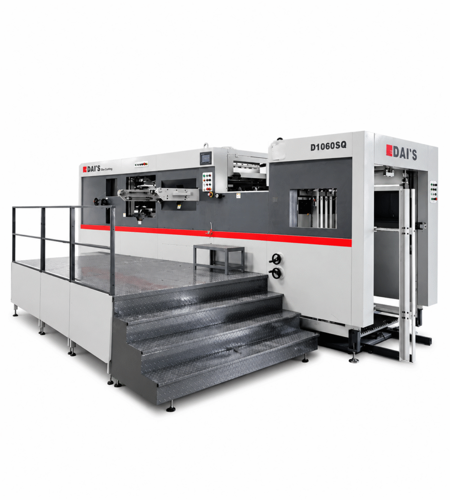
The force from a die cutting machine must be transferred evenly to the die, sheet and cutting plate, but can only do this if the machine is structurally stable when loaded. The ductile iron frame in die cutting machines is part of that structural support, to help distribute pressure evenly over repeated cuts and to resist unwanted deflection. But frame accuracy is not the only thing that can affect cutting accuracy. The result is determined by material condition, rule sharpness, make-ready, registration, lubrication and operator setup.
A heavier machine is not necessarily more accurate, nor is a ductile iron frame wear-proof, poorly set up or board-proof. A key point to note is that the entire mechanical system must handle load, alignment and repeatability in real production.
Why Machine Rigidity Matters in Flatbed Die Cutting
In flatbed or platen die cutting, the machine needs to exert a controlled cutting force against a die layout, and all parts on the press (die frame, cutting plate, sheet path) need to be in stable alignment. A rigid structure can withstand bending, twisting and loads during operation. This will help keep the conditions as uniform as possible between strokes, particularly in the case of large sheets, dense dies and long runs.
What Happens During a Die-Cutting Stroke
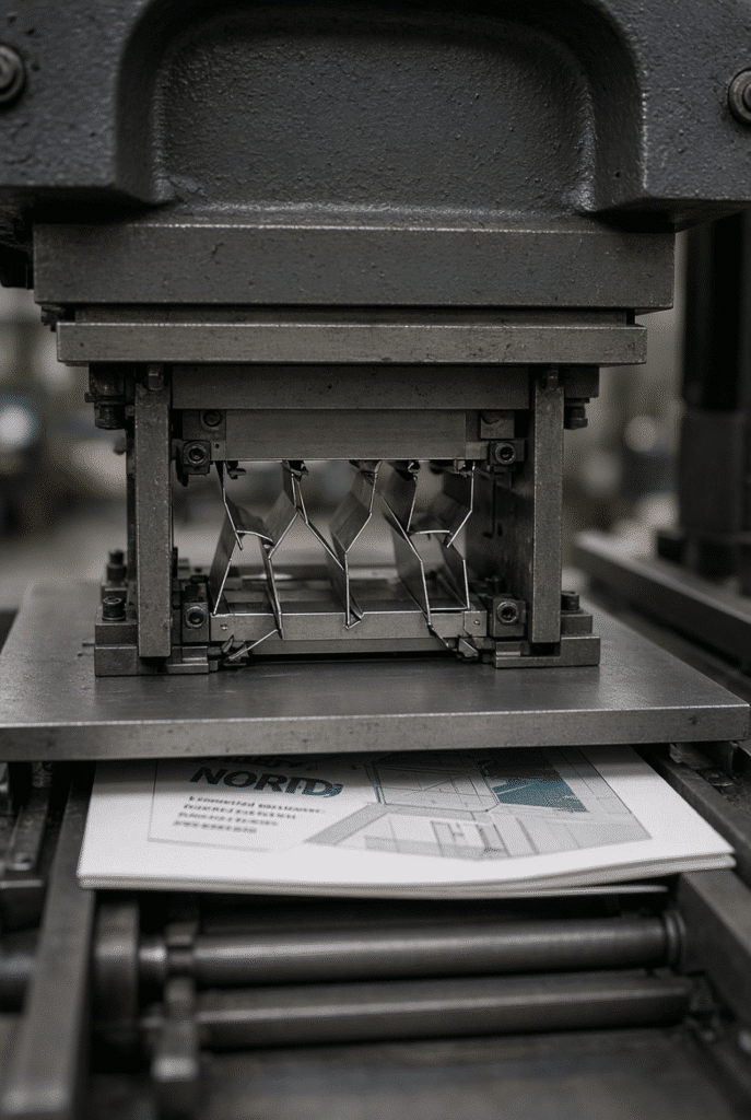
A sheet is fed and registered. The platen closes. The rules for cutting and creasing are applied to the board. Press is opened for delivery and next cycle. During the compression stroke, the force is transmitted through the frame, platen, drive system, die frame, cutting plate and tooling assembly. A layout that is complex folding carton can include cutting rules, creasing rules, perforation, windows and waste bridges. These components produce various resistance in the sheet. The structure should be able to distribute control forces during opening and closing thousands of times.
Deflection, Pressure Distribution, and Uneven Cutting
Deflection: The slight movement of the structure when loaded. As deflection gets excessive or uncontrolled, the pressure distribution might become uneven. This can manifest itself in the form of incomplete cuts, hanging fibres, inconsistent crease depth, pressure marks or recurring adjustments of make-ready. Not all cut points are necessarily frame points. These symptoms can also result from the condition of the die, worn cutting plates, packing errors, poor make-ready, variation in board thickness, misregistration or incorrect pressure settings. Systematic diagnosis should be made.
Rigidity Matters More on Demanding Jobs
The machine structure is put under greater stress when larger sheets are used, layouts are dense, paperboard is thicker, some corrugated products are used, the length of the cutting rule is long, the creasing is more complicated, and high volume repeat runs are used. Many cartons can be run satisfactorily on a simple small carton. A large multi-up print will show any weakness of the tooling, set-up, material preparation or pressure consistency much more evident than any other method. Therefore, it is important to take a closer look at how machines are built, as the tasks become more challenging.
Ductile Iron in Die Cutting Machine Frames and Pressure-Bearing Components
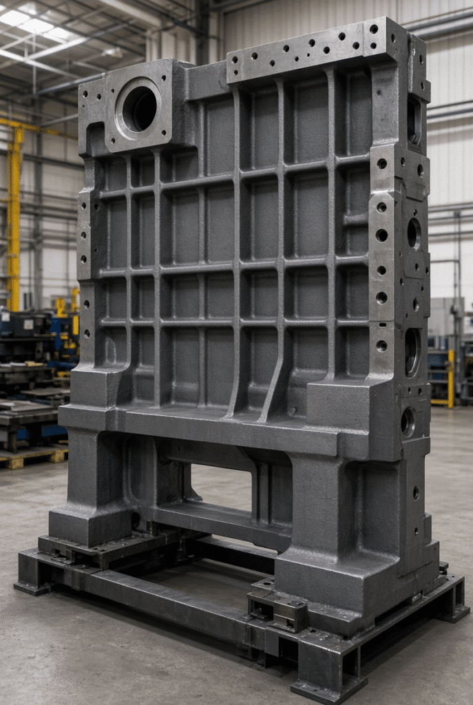
The family of cast irons known as ductile iron, or nodular, or spheroidal graphite iron, has a graphite microstructure which can give desirable combinations of strength, toughness and castability for specific machine parts. It has engineering properties unlike conventional gray cast iron, and these are dependent on grade, composition, casting method, heat treatment, geometric shape and quality control. It is used in industrial machinery in situations where designers require complicated cast geometry with a well-balanced set of mechanical properties.
The ductile iron frame can be the main frame, wall plates, pressure-bearing castings, platen-support castings or other castings that provide structural support. Buyers should inquire precisely which parts are made of the material, what grade is required, and what casting, heat-treatment and machining controls are in effect.
What QT600-3 Means—and What It Does Not Mean
QT600-3 is a popular ductile-iron grade used in China. In general, the numbers are the specified minimum tensile strength and elongation. The minimum values for tensile strength, yield strength and elongation published under the relevant standard context are 600 MPa, 370 MPa and 3 %, respectively. The following figures are standard reference properties of the material grade. They are not a guarantee of in-service strength, stiffness, dimensional stability, and fatigue performance of any specific finished machine part. Final performance is influenced by the geometry, wall thickness, casting quality, cooling control, stress relief, machining, assembly, and actual operating load.
Why Cast Structural Components Are Used in Industrial Machinery
Cast structural components enable the designer to achieve a high degree of repeatability, complexity, incorporation of mounting surfaces, ribs and housings, and production that may be more complicated or less efficient than other methods. Both cast and fabricated-steel structures can be engineered successfully. The buyer must be concerned about the proper design, production, machining, assembly and testing of the structure for the intended load and duty cycle to be applicable for die cutting.
Material Selection Is Only One Part of Structural Rigidity
The whole design of the structural design including geometry, ribbing, wall thickness, span length, platen support, load path, fastening methods, machining accuracy and alignment controls the rigidity. If a high spec material is used in a weak geometry, it will not provide the required rigidity. The use of carefully designed geometry and controlled manufacturing can yield better structural performance. Questions to ask, besides the obvious “Is the frame ductile iron?” are: Which parts are cast? What grade is used? How are the casts checked? What is used to cut critical surface? What mechanisms are used to keep the parts aligned when putting them together? What kind of testing is done prior to shipping?
How Frame Rigidity Influences Die-Cutting Accuracy and Creasing Quality
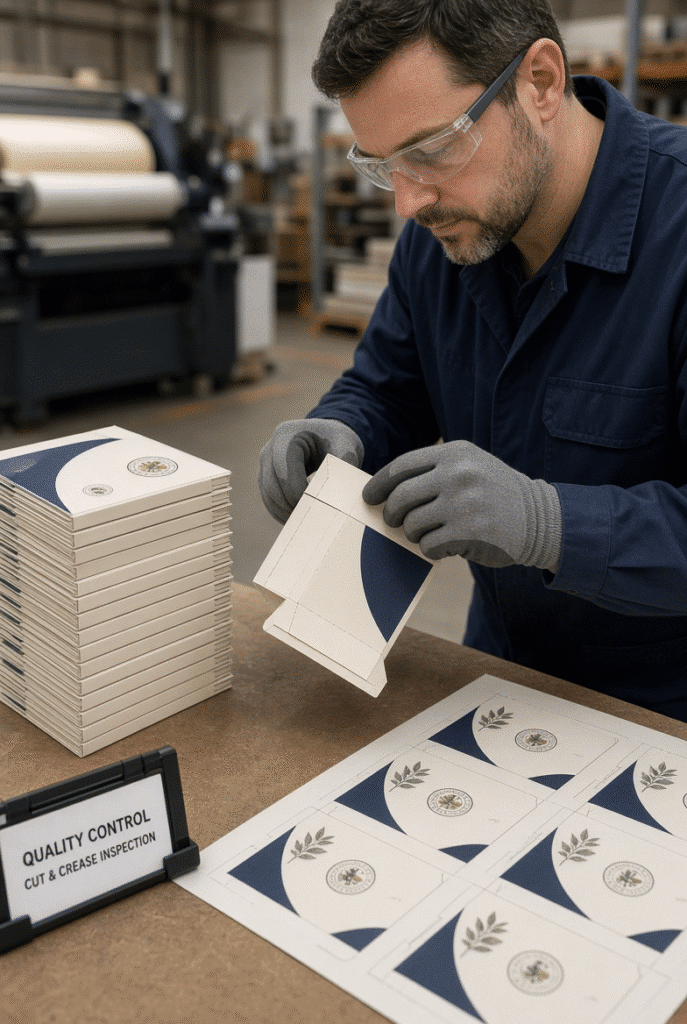
A stable press structure allows for better pressure distribution and repeatable movement. These conditions help to ensure clean cutting, consistent creasing, controlled perforation and print-to-die alignment. Frame rigidity facilitates the process, it does not take the place of process control. Printed-sheet stability, die preparation, creasing matrix, cutting plate and machine settings still have a major impact on finished carton quality, even when using paperboard and moisture conditions.
Clean Cutting Across the Full Sheet
Inadequate pressure can manifest itself in some areas as undercut, corners not being cut, fiber pull, inconsistent waste release, or over-packing specific sections of the die. A stable structure gives a more stable base for the cutting to be done in a consistent manner, but the operator must still perform a condition check of the die and a make-ready operation. Possible causes for having a problem with the center cutting nicely, but only the edges showing hanging fibers are pressure distribution, die wear, cutting-plate wear, uneven packing, sheet variation, or machine alignment. Firstly investigations are conducted before an overall increase in pressure is made.
Creasing Consistency and Carton Folding Performance
When creating a fold, the most important factor is to apply the compression in a controlled manner, rather than with all your force. A difference in crease depth can cause cracks to form in printed or coated surfaces, or not form the crease correctly, or create an uneven shape in the carton, or cause a loss of appearance after creasing and gluing. Repeatable press conditions are provided by a rigid structure, but the resultant crease will depend on the direction of grain on the board, the type of board, moisture content, selection of a crease rule, choice of matrix, make ready, and adjustment of pressure. The finished folded carton – the sheet itself – should be judged.
Registration Stability in Printed Packaging
The primary factors affecting print-to-die alignment consist of sheet feeding, front and side registration, transport control, grippers handling and die setup and materials consistency. While it is true that frame rigidity can help to ensure stable machine behaviour, it is not the only factor in determining the accuracy of registration. A die-cut window in a cosmetic carton with a narrow printed border around the window may not even pass visual inspection due to a slight deviation from the sheet position. All of the registration chain from the feeders and the lay section to the die-cutting area and delivery needs to be analyzed.
The Structural System Behind a Rigid Die Cutting Machine
It’s not a standalone frame. Machine rigidity is a system comprised of main structure, platen, pressure bearing parts, crankshaft, worm gear, intermittent mechanism, bearings, die frame, cutting plate, lubrication and assembly alignment. Heavy duty construction claims are best complemented by component lists and engineering drawings.
Platen, Pressure-Bearing Parts, and Load Path
The force is transmitted to the platen and supporting structure via the cutting area of the die. The motion of the force should be directed through suitable components and should follow a specified path, whilst ensuring that particular positions of cutting surfaces are kept in a fixed relationship. Buyers should inquire about the method of platen support; the materials used in pressure bearing parts; and the accuracy of the parts in the machining and assembly process.
Crankshaft, Worm Gear, and Intermittent Mechanism
The main drive and transmission parts have an impact on timing, motion repeatability, pressure delivery and long term operating characteristics. Design and maintenance of crankshaft, worm gear, bearings and intermittent mechanisms are needed to ensure stable cycles with repeated loading. The buyer must not attempt to calculate gear loads but he must be aware of the importance of the considerations mentioned above for the manufacturer’s machining capability, lubrication design, sourcing of components, inspection and maintenance guidance.
Bearings, Lubrication, and Long-Term Alignment
Inadequate lubrication, fasteners, wear-out bearings and lack of maintenance can destroy the ability of an even good frame to maintain expected performance. Movement in critical assemblies is facilitated by lubrication systems, and regular inspection can detect wear without it impacting on cut quality or reliability. Consumables, maintenance schedules, documentation of troubleshooting, serviceability, lubrication points, and the availability of spares are all questions that should be asked of a buyer.
The Die Frame, Cutting Plate, and Make-Ready Interface
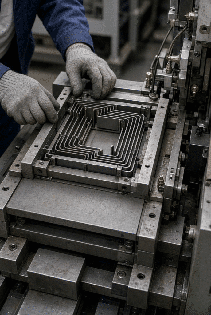
The area where the machine meets the tooling is important. The way machine force is transferred to the sheet is decided by the die frames, the cutting plates, the packing, the rules, the make-ready preparation and the creasing matrix and the ejection rubber. Poor die, damaged cutting plate, make-ready and packing problems cannot be overcome with a rigid machine. These are all part of the same quality system.
Common Accuracy Problems That Are Mistakenly Blamed Only on the Frame
Structural issues are clearly differentiated from tooling, set-up, material, feeding, registration and maintenance issues through disciplined diagnosis. This allows production teams to limit the need for excessive and futile reactions, like applying pressure.
Incomplete Cuts and Hanging Fibers
The likely causes are either pressure not being sufficient or the pressure applied is uneven, or rules are dull, or the cutting plate is worn or the die is damaged, or packing is incorrect, or the boards are not of the correct thickness, or the moisture content of the material is changing, or the make-ready is wrong. Operators should note whether the defect is present in the same area of the die, same area of the sheet, same material batch, or comes after the machine has run for a given amount of time. Once the cause has been narrowed, pattern recognition takes over.
Cracked Creases, Crushed Flutes, and Surface Marks
Packaging material can be damaged by excessive pressure, improper crease rules, improper matrix selection, poor material condition, improper grain direction or over-packing. Excessive compression may have detrimental impact on the flute structure and finished-packaging strength of corrugated board. Increasing the pressure may temporarily help to improve cutting but may have a detrimental effect on creasing or surface quality. Quality of cuts and quality of folding should be judged together.
Registration Drift and Uneven Die-to-Print Alignment
Vibration, noise or changes of output may be signs of lubrication, bearing, transmission, fastener, die condition, material flow or maintenance problems. It is important to recognize these signs and do not shrug them off as the normal high-speed operating of a machine. Perform maintenance as specified by the manufacturer, note any unusual situations and have qualified technical assistance diagnose conditions before they worsen.
Vibration, Noise, and Changes Over Long Runs
Unusual vibration, noise, or output changes can indicate issues with lubrication, bearings, transmission, fasteners, die condition, material flow, or maintenance. These symptoms should not be ignored or dismissed as normal high-speed operation. Follow the manufacturer’s maintenance instructions, record abnormal conditions, and seek qualified technical evaluation before defects accumulate.
How Buyers Should Evaluate Frame Construction Before Purchasing
Purchasers do not have to be a foundry expert, but they should be aware of what type of evidence and questions will help them determine if a manufacturer’s construction claims are meaningful. Compare similar machine setups and inquire about information pertinent to the materials, die designs, pressures, and goals of the intended use.
Questions to Ask About Frame Material and Structural Design
Useful questions include:
- What components are made of ductile iron, cast iron, fabricated steel or other materials?
- What is the grade of material used for components that are subject to pressure?
- What are the key principles of the construction of main frame and platen?
- What methods are used to check castings for defects and dimensional control when they are large?
- Do critical surfaces get machined after casting and stress-relief?
- Which side of the die-cutting section is facing up when it is put together?
- What quality tests are done prior to shipping?
- What maintenance practices are needed to maintain structural and motion accuracy?
A good supplier responds with clear technical information, drawings, photos or documented process descriptions, not with general promotional statements.
Review Real Machine Evidence and Similar Applications
Request pictures or video of the appropriate model of the machine being machined, assembled, tested and operated. Ask for examples of similar paperboard or packaging applications, such as dense die layouts, strict tolerances, large size, laminated die and appropriate corrugated board. While anonymized examples, relevant test data, running videos and sample discussions still give an idea of how well the manufacturer understands the application.
Test With Representative Material and Die Layout
A meaningful trial should be conducted on the buyer’s material or representative material, and, if possible, a similar die layout. The test should include the following parameters: sheet feeding, registration, cutting quality, crease quality, waste release, stack delivery, sustainable running speed, repeatability across multiple cycles. No short-term trial can tell you everything you need to know about the long term, but a well-documented trial is more useful than just what’s in the frame-material claims or the brochure’s specifications.
A Practical Checklist: Rigidity, Accuracy, and Machine Selection
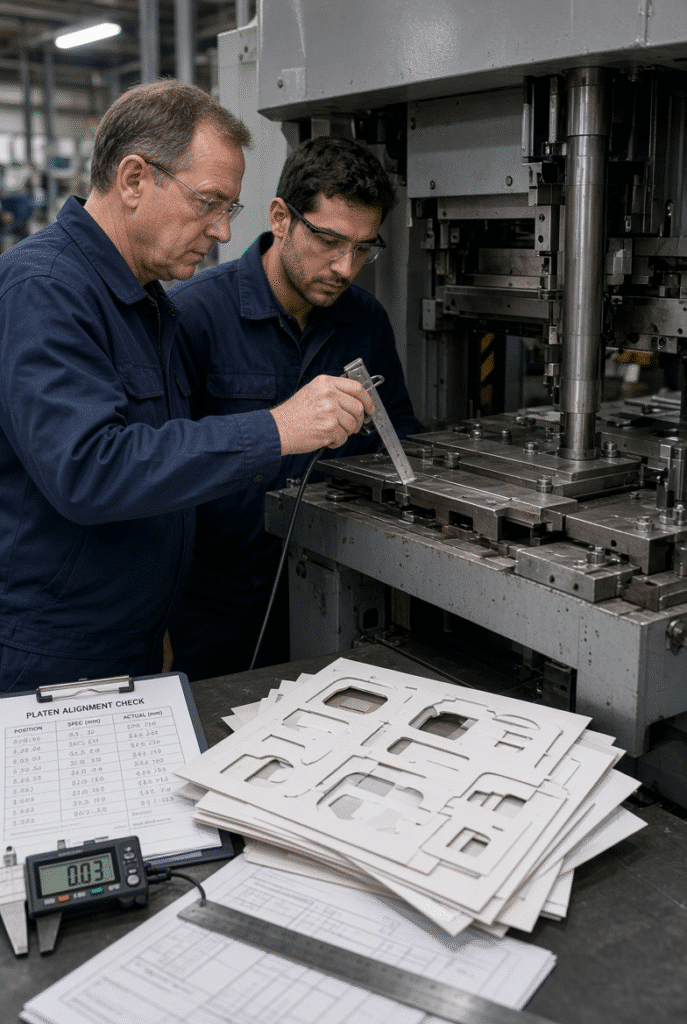
Refer to the following reference when comparing suppliers, conducting a technical analysis or visiting the factory. Every line promotes documentation, examination of evidence and review of the full machine system instead of individual claims.
| Evaluation Area | What to Review | Why It Matters in Packaging Production |
| Main frame structure | Material, geometry, wall plates, ribs, and pressure-bearing design | Supports controlled movement and resistance to unwanted deflection under working load |
| Frame material claim | Exact material grade and which components use it | Helps distinguish a documented construction detail from a vague marketing statement |
| Casting and machining | Evidence of casting quality control, machining, and critical-surface finishing | Influences alignment, assembly consistency, and component fit |
| Platen and load path | How press force is transferred through the die-cutting section | Affects pressure distribution across the die and sheet |
| Drive and transmission | Crankshaft, worm gear, intermittent mechanism, bearings, and service access | Supports repeatable motion and long-term operating stability |
| Tooling interface | Die frame, cutting plate, packing, creasing matrix, and make-ready process | Directly affects how machine force becomes cutting and creasing quality |
| Feeding and registration | Feeder, front lay, side lay, gripper, transport, and detection systems | Determines whether sheets arrive consistently for accurate die cutting |
| Lubrication and maintenance | Lubrication design, inspection intervals, spare parts, and maintenance access | Helps preserve mechanical condition and reduce quality drift over time |
| Trial evidence | Representative material, relevant die layout, documented results | Provides application-specific evidence beyond general specifications |
| Service support | Manuals, drawings, training, technical response process, and spare parts | Reduces long-term risk when quality or mechanical issues need diagnosis |
Organize a comparison of suppliers using the same checklist. It’s not a matter of which machine is heavier or which frame is of better material. Examine the evidence to support the design, manufacture, testing, tooling interface and support process.
Final Guidance: Treat Rigidity as Part of a Complete Die-Cutting System
Ductile iron frame construction may also be applicable to die-cutting machine rigidity, but it cannot be said to be a guarantee of accuracy. Good cutting and creasing requires the entire system—from structural design to pressure-bearing components, transmission, tooling, material condition, register, make ready, lubrication, inspection and operator practice.
Buyers should ask detailed questions, look for actual evidence of manufacturing, and test the product using representative packaging material and die layouts. It’s not just about the frame material, it’s about the proven application and configuration.
The D1060S is an automatic flatbed machine that indicates the combination of these elements in one industrial configuration and allows to obtain a maximum working pressure of 300 tons, and an accuracy of pressure-bearing parts of ±0.1 mm under suitable production conditions, with a specification of QT600-3 ductile iron for pressure-bearing components. Please submit material type, sheet size, board thickness, layout of the dies, print-registration requirement, output quantity and sample products for technical review of the appropriate configuration of the die cutting machine.