

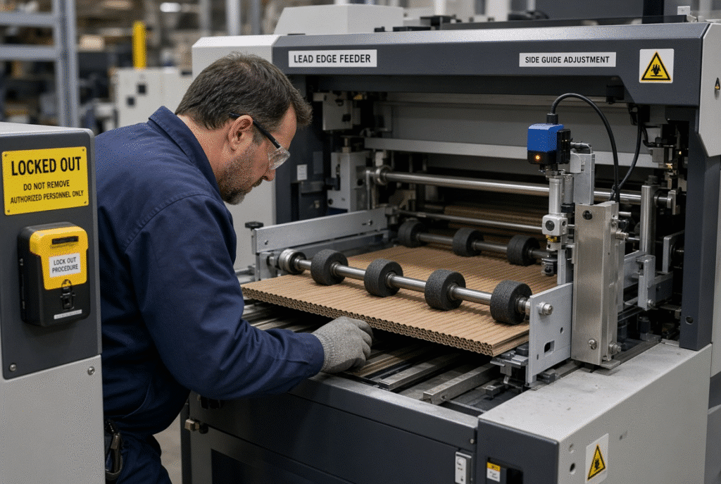
Reliable lead edge feeder maintenance keeps sheet separation stable, engagement consistent, and positioning accurate on flatbed die cutting machines handling corrugated and paperboard. Regular inspection of feed wheels, separation components, sensors, guides, support surfaces, gauges, timing, and—where the machine is fitted with them—vacuum components reduces double feeding, missed feeds, skew, jams, and registration variation before they interrupt production.
These problems rarely appear without warning. Worn wheels can look like a material issue, dirty sensors can mimic timing faults, and misaligned guides can create the same symptoms as board warp. Base every check on the machine manual, the boards actually running, production hours, and the plant’s own fault history rather than a one-size-fits-all schedule.
Before any inspection begins, stop the machine, isolate electrical, pneumatic, hydraulic, vacuum, and stored mechanical energy according to site lockout/tagout rules, wait for all motion to cease, and verify that components cannot restart unexpectedly. Never reach into the feeder while parts are moving, and never bypass guards, interlocks, or emergency stops.
What a Lead Edge Feeder Maintenance Program Should Cover
A practical program is not just a pair of feed wheels to wipe every once in awhile, it’s a complete sheet-handling system. It features material-path cleaning, wear detection, sensor verification, guide and gauge alignment, sheet-support checks, vacuum checks (if vacuum is used), lubrication in accordance with the manual, drive and timing checks, safety device checking, and basic job record information.
Every item is directly linked to a production risk. Slipping is due to contaminated wheels. Missed detection or false detection results from dirty sensors. Loose guides: skew. Weak vacuum (where installed) decreases pick up reliability. Skewed support allows for flexing or catching of the sheets. Without lubrication there is noise and wear. An incomplete record doesn’t reveal any deterioration until the next long stoppage.
Daily Operator Checks
Operators can safely check for visible paper dust, adhesive residue, ink or coating buildup on wheels and guides, obvious flat spots or cracks on feed wheels, cleanliness of the sensor lens, debris in the stack area, unusual noise/vibration, and clear surface damage on support tables. These checks are made at the beginning or end of a shift while the machine is stopped and energy isolated. Operators do not open guarded areas, make electrical or pneumatic adjustments or replace internal components without permission.
Periodic Maintenance Checks
Periodic inspections by trained personnel are required to be performed in accordance with the service schedule provided for the machine in question for bearings, belts, chains, drive components, sensor mounting, vacuum elements (if installed), and geometric alignment. Intervals will depend on production time, board dust load, adhesive usage, etc., and on the actual configuration. Don’t follow another plant’s timing, always follow the manufacturer’s instructions.
Maintenance Records and Symptom History
Write down the board type, flute, thickness, sheet size, running speed, feeder setup, number of defects, parts replaced, sensor fault codes and precise maintenance performed. These notes show patterns over time that are not apparent in a single pass of a visual inspection, e.g., wheels wearing faster on some laminated stocks, or sensors drifting after a large quantity of adhesive runs.
Safety Before Lead Edge Feeder Maintenance
A safe machine state is the starting point for maintenance. All the subsequent checks rely on this.
Stop, Isolate and Verify
Slowly stop the machine. Separate power supplies, air lines, hydraulic pressure, vacuum sources and any stored spring or gravity power. Wait until all the rotating and reciprocating components come to a stop. Test for isolation using the correct methods prior to any access.
Guards, Interlocks and Emergency Devices
Do not override a guard, interlock, light curtain or emergency stop to allow output to continue. A safety-device fault is a service fault that requires a qualified person’s attention. Transient loss of these systems results in unarranged dangers and invalidate normal operating assumptions.
Operator Checks Versus Qualified Service
Simple condition observations, approved external cleaning, and visual inspection are normal operator responsibilities. Tasks that involve electrical panels, control parameters, servos or drive settings, structural alignment, or replacement of guarded components are for trained technicians or manufacturer service people.
Feed Wheel and Brush Wheel Maintenance
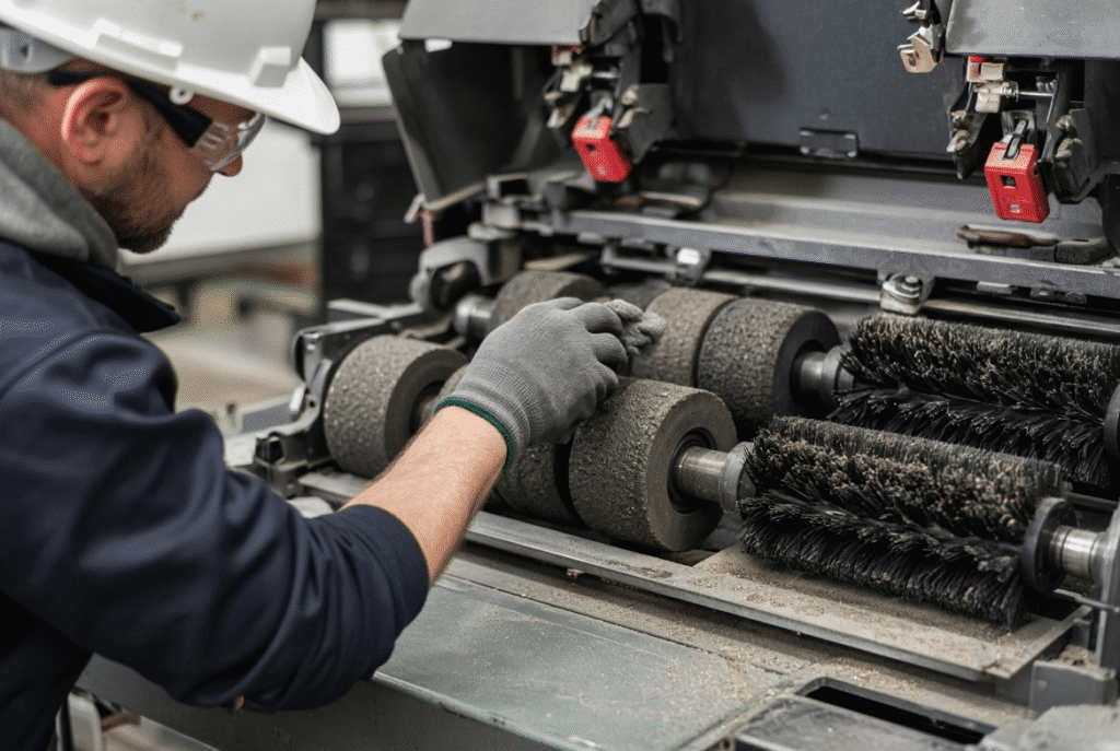
Initial sheet pickup, transport force, surface condition and feed pitch consistency are controlled by feed wheels and brush wheels. As a result, it’s their condition that is the first mechanical check most technicians perform.
Inspect Feed-Wheel Wear
Check for flat spots, cracks, unequal diameter, hardened or glazed surfaces, loss of grip texture, embedded contamination, loose mounting hardware and unequal contact left-to-right. All of these conditions can cause slipping, missed feeds, irregular pitch, skew, surface marks, or gauges not being reached in a timely fashion.
Clean Feed Wheels Correctly
Clean with products, tools and techniques specified in the machine’s manual. Scrape and remove paper dust, ink, coating and adhesive residue without abrading or chemically attacking the surface of the wheel. Solvents not approved for use can cause hardening of rubber compound or leave a film which may cause slip.
Check Wheel Height and Contact Pressure
Double feeding, edge damage, surface marking or skew may occur if the height is not correct or if excess pressure is used. Check for parallelism of wheels and adjust to the manufacturer’s reference prior to adding pressure. Allow one variable to vary and test using representative production sheets.
Inspect Brush Wheels and Separation Components
Examine worn or bent bristles, board height, contact pressure, dust packing and separation settings. The geometry of brushes should be based upon the quality and condition of the boards being used.
Know When Replacement Is Required
Sensor Cleaning and Detection Checks
Sheet presence, spacing and in some cases double sheet conditions are confirmed by sensors. Do not correct mechanical misalignment, extreme warp or worn wheels.
Common Causes of Sensor Detection Problems
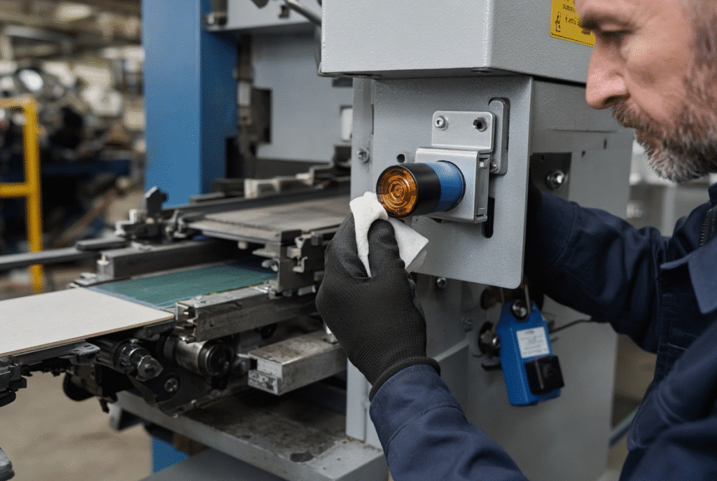
Paper dust, adhesive or coating residues, mounting heights on printed surfaces and mounting angles, loose brackets, highly reflective printed surfaces, very dark printed surfaces, damage to the cable, and drifts in the control parameters all cause missed detections, false alarms, empty cycles, or inconsistent timing signals.
Clean and Inspect Sensors Safely
When the unit is shut off and isolated, clean the lens or sensing face with approved materials and methods. Inspect the mounting and to ensure the cable is not damaged. Never change electrical sensitivity or timing parameters without assistance.
Verify Detection with Test Sheets
Once the machine is safely back in operation, test representative sheets of various types (glossy, dark, laminated, and heavily printed) and see if detection remains the same. Optical properties can influence some of the photoelectric sensors even with the mechanical path in place.
Sensor Problems Versus Mechanical Problems
A clear, properly placed sensor will only relay what it is seeing. It will not correct out of square wheels, guides or due to poor support or damaged lead edges. Never assume that the sensor should be replaced without checking the physical path of the sheet.
Vacuum System Checks Where Applicable
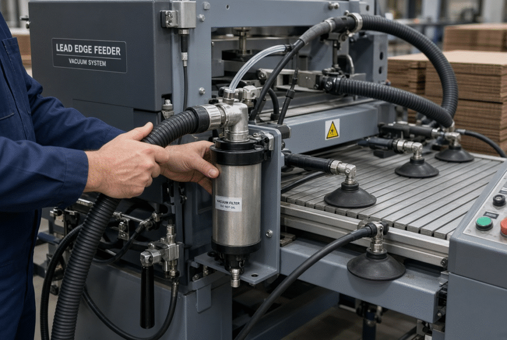
Vacuum checks are only required where the lead-edge feeder/sheet-separation is vacuum-assisted, e.g., equipped with a pump, hoses, vacuum-assisted belts or chambers or a vacuum sensor. Many lead edge systems do not operate in a vacuum; do not assume it is.
Vacuum Pump and Airflow Condition
If vacuum pump is installed, listen for unusual noises, check for decreased air flow, inspect filters, and observe overheating. Only follow inspection points and procedures provided in the machine manual.
Hoses, Seals and Vacuum Leakage
Loose fittings, cracks on hoses, damaged seals or open ports will decrease the available vacuum and result in missed sheet pickup, missed feeds, or unstable transport. Systematically check connections when the system is isolated.
Suction Belts, Holes and Chambers
For machines equipped with suction belts or suction chambers, inspect for blocked holes, belt deterioration and tracking problems, contamination of the chamber, and sealing problems. These elements are only available on certain configuration feeders and not on all lead-edge feeders.
Vacuum Versus Board Condition
Even if the system is good, leaks can occur in the corrugated board due to porosity, warping, or unevenness, thus reducing the good vacuum. Prior to diagnosing a vacuum fault, compare actual performance to representative production sheets that are flat.
Alignment Checks for Guides, Gauges and Sheet Support
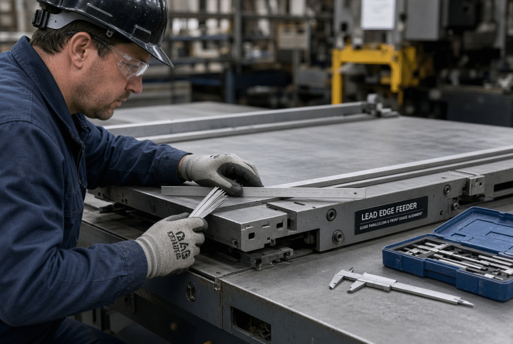
Even if wheels and sensors are in good condition, alignment issues can cause skew, jamming, rubbing on surfaces and registration variance.
Guide Alignment and Clearance
Ensure side guides are parallel, properly positioned and are clean with no rough edges and have proper clearance for the board thickness. Loose guides will allow for drift, while too tight guides can rotate or cause damage to the sheet.
Front-Gauge and Side-Gauge Alignment
The front and side gauges set the sheet reference position prior to the Die-Cut cycle. Determine position, parallelism, contact state and suitability for the current sheet format. Only qualified personnel should make the machine adjustments that could impact machine geometry or registration accuracy according to the manufacturer’s procedure.
Sheet-Support Surface and Transition Checks
Examine support tables, belts and transition areas between the pile, feeder positioning system, die-cutting section, delivery. Sheets flex, catch, or lose control over gaps or height changes, or when the board is warped.
Operator-Side and Drive-Side Comparison
If the operator side and drive side don’t wear or adjust evenly, then there is skew or uneven contact. Look at several contiguous sheets and test both sides before applying pressure throughout the feeder.
Lubrication, Drives and Mechanical Movement
Lubrication and Drive checks are used to ensure a smooth movement and to reduce wear. They are NOT an opportunity to grease all the visible surfaces.
Approved Lubrication Points
Use the lubricant type, amount and frequency recommended for each point in the machine manual. Too much oil, or the wrong type, will cause contaminated feed wheels, belts, sensors and printed sheets.
Chains, Bearings and Drive Components
Check for any fasteners that are loose, check for any signs of wear on the chains and look for abnormal sounds or vibration, as well as inconsistent movement or backlash. Do not model-independent adjust drive synchronization issues; these issues must be diagnosed by a qualified person.
Lubrication Contamination Risks
Any electrical faults, drive problems, bearing problems, structural misalignment or timing issues and control problems must be addressed by trained personnel or the machine manufacturer.
When Qualified Service Is Required
The table below provides a set of common symptoms to the most useful first inspection points. This is only a starting guide, the machine manual is the definitive guide.
Maintenance Checks by Production Symptom
The following table links common symptoms to the most useful first inspection points. It is a starting guide only; the machine manual remains the authoritative reference.
| Symptom | Primary Inspection Areas | First Practical Checks |
| Double feeding | Separation components, brush settings, pile pressure, sensors, board condition | Clean and set brushes/wheels before increasing pressure |
| Skewed sheets | Unequal wheel contact, guide alignment, side-gauge pressure, support surfaces, board warp | Compare operator-side vs drive-side, verify guide parallelism |
| Missed feeds | Wheel grip, sensor cleanliness, timing, vacuum (if fitted), lead-edge condition | Clean sensors and wheels, confirm vacuum only if installed |
| Paper jams | Pile alignment, edge curl, guide clearance, support gaps, transitions | Identify the first contact/jam point before changing settings |
| Surface marks | Contaminated or worn wheels, excess pressure, rough guides, lubricant leakage | Inspect full contact path from feeder to delivery |
| Registration variation | Gauge alignment, sheet skew, feed-pitch consistency, board warp, wheel wear | Check feeder-to-die handover after correcting skew |
Double Feeding
Begin with separation and brush settings, then look at pile pressure, static or adhesive sticking. Clean and realignment before just increasing the force of contact.
Skewed Sheets
Common causes are unequal wheel height or guide misalignment or support difference from side to side. Ensure geometry is correct before increasing overall pressure.
Missed Feeds
Empty cycles are the result of wheel slip, contaminated sensors, timing drift, weak vacuum (if applicable) and damaged lead edges. Check out the physical route first.
Paper Jams
Find the first contact or restriction. Common causes are pile alignment, guide clearance, and transition gaps.
Surface Marks
Adjust pressure after following the entire contact path: Wheels, Guides, Support surfaces and any lubricant leakage.
Registration Variation
Downstream registration issues may be caused by skew, inconsistent feed pitch, and gauge position.
Preventive Maintenance Schedule and Documentation
Investigate a preventive maintenance schedule and documentation system.Research a system of preventive maintenance schedule and documentation.
Before Each Shift or Job
Verify the cleanliness of material path, condition of the feed wheel, position of the guide, condition of sensor lenses, cleanliness of the stack area, condition of support surfaces, and no obvious leaks or damage.
During Production
Watch feed stability, sheet pitch, registration, surface quality, sensor alarms, noise, and vibration. Gradual changes often signal developing wear or contamination.
During Planned Maintenance
Bearings, belts, chains, drives, sensors (if fitted), vacuum components (if fitted), lubrication points, alignment, safety devices and wear parts are inspected by trained staff as per service schedule.
Record Parts, Settings and Defects
Log the model of the log machine, board type and flute, thickness, sheet size, log speed, feeder settings, any faults observed, components replaced, cleaning and alignment actions, date and who did the work. These records enhance consistency in changeovers, and show recurring wear patterns.
How Maintenance Affects Machine Selection and Ownership Cost
When considering a new lead-edge feeder, you want to consider more than just maximum speed and format. Long-term uptime and ownership cost are directly impacted by service access, the availability of spare parts, documentation quality, training and supplier response time.
Ask About Wear Components
For vacuum configurations, inquire about how the pumps, filters, hoses, belts and chambers are accessed and maintained. It is also important to have access for mounting and cleaning sensors.
Ask About Sensors and Vacuum Components
Where vacuum is part of the configuration, ask how pumps, filters, hoses, belts, and chambers are accessed and maintained. Sensor mounting and cleaning access are equally important.
Ask About Alignment and Training
Explain alignment of guides, gauges and sheet support systems and training of operator and technician that comes with the machine.
Ask About Spare Parts and Technical Support
Ensure feed wheels are available, brushes, sensors, belts, bearings, approved lubricants and technical documentation are available, as is realistic response time and service.
D1060Y Maintenance and Technical Support
The D1060Y is a flatbed type die cutting machine for paperboard and corrugated board, which is made for lead edge feeding. Each machine will have different maintenance needs depending on the final configuration, number of production hours, board condition and specific components fitted. For inspection, lubrication and adjustment procedure follow the machine specific manual. When the work would include electrical, pneumatic, drive, control, vacuum (if fitted), alignment, structural components or if the configuration is not clear, contact DAIS technical support.
Frequently Asked Questions About Lead Edge Feeder Maintenance
How often should lead edge feeder components be inspected?
Frequency is related to machine manual, daily production hour, dust load, adhesiveness and plant’s own fault history. Make simple, regular observations of the operator instead of copying intervals from another model; do not use a periodic qualified observation.
When should feed wheels be replaced?
Change when flat spots, cracks or hardened surfaces are noticeable, when thorough cleaning and proper adjustment do not stop slipping, when feed length is not consistent, or when the wheels start to mark the surface of the sheet. It’s the moment that is determined by condition not by fixed hours.
How do dirty sensors affect feeding?
When dust, ink, adhesive, residue from coating, or improperly positioning, creates missed detections, false alarms, empty cycles, or irregular timing signals, the detector will be ineffective. Safely use the machine to clean the sensing face, and check the detection by using representative production sheets.
Does every lead edge feeder use vacuum?
No. No vacuum pumps, hoses, suction belts or chambers are found in all configurations. Please check these components only when these items are installed on the machine under evaluation.
What causes skew after feed-wheel maintenance?
This is caused by the various reasons, such as uneven wheel height or pressure left to right, misaligned guides, incorrect side-gauge position, problems with support surfaces, incomplete reassembling, or board warp. Always test alignment before adding more pressure.
Can lubrication cause surface marks?
Yes. Too much lubricant, or leakage, may flow into feed wheels, belts, guides or the sheet itself, causing slip, stains, or marks. Only use the approved product at the specified locations and amounts specified in the manual.
What maintenance can operators perform?
An operator can perform an approved visual inspection, exterior cleaning and perform simple machine condition checks in a safe and isolated condition. Work involving electrical, pneumatic, drive, control, structure, and guarded-components must be carried out by trained persons.
When should I contact the machine manufacturer?
Call the manufacturer if there are persistent faults after approved checks, if the alignment and timing are not known, if safety devices or control systems are used, if parts of the machine are liable to damage, or if the configuration of the machine is unknown.
Summary Guidance – Maintain the Feeder Before Faults Become Downtime
Effective lead edge feeder maintenance is achieved by material-path cleaning, wear inspection of feed and brush wheels, proper maintenance of sensors, vacuum checking only in situations where sensors are present, checking of guides, gauges and support surfaces, manufacturer-recommended lubrication, safe isolation procedures, symptom-based diagnosis, and accurate records.
Use a stopped and isolated machine. Check the wheels and brushes first. Clean sensors properly. Confirm vacuum only if there is a vacuum included in the configuration. Verify geometric alignment. Apply the proper lubricant at the proper locations. Trouble shoot from the first failure point outwards. Record settings and interchangeable components. Take all checks beyond approved operator checks to qualified service. Always Read and Follow the machine specific manual.
If the machine is a D1060Y lead edge feeding flatbed die cutting machine, refer to the machine documentation or contact DAIS technical support for parts or technical questions specific to the machine.