

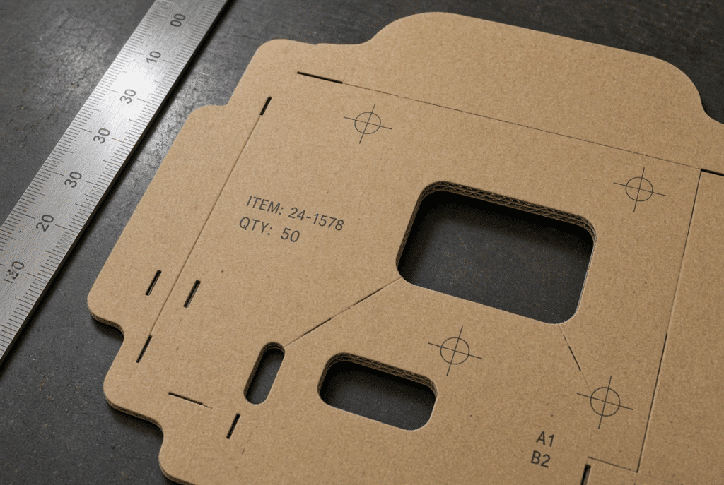
No single type of feeder can be recommended as the best for corrugated board die cutting. It depends on the thickness of the board, the flute construction of the board, the size of the sheet, the warp of the board, the surface of the sheet after being printed or laminated, the requirement of registration, the requirement of production speed, the design of the machine, the maintenance capacity, and the test results of the sample with actual materials. A lead edge feeder is used to control and move the front edge of the sheet, a bottom suction feeder is a vacuum from beneath the sheet to lift or move the sheet. There are machines that have mechanical lead-edge control and suction assistance. Buyers should make comparisons on a system level and not just based on feeder name.
What Is the Difference Between Lead Edge and Bottom Suction Feeding?
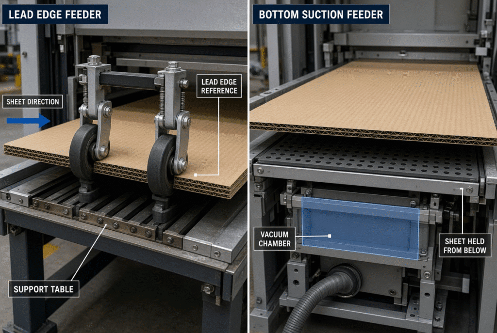
The first difference is the way in which each system is transferring the sheet from the pile to the die-cutting station. The reference edge and the transport method is called lead edge feeding. The lifting or holding force as in sucking from the bottom is known as bottom suction feeding. These are just guidelines, not full machine setups. They still rely heavily on support tables, gauges, sensors, timing, and overall machine design to ensure optimal performance.
How a Lead Edge Feeder Controls the Sheet
A lead edge feeder is usually used to separate the top sheet from a pile, and is used to engage the leading edge with feed wheels or other types of feed engagement elements, and to move the top sheet along a supported path. Timing and presence of sheets confirmed by sensors. This sheet is then brought into contact with front and side gauges, which fix the final position of the sheet before the die-cutting cycle starts. This front-edge arrival under control of the board and machine setup helps to ensure repeatable sheet positioning and stable registration.
How a Bottom Suction Feeder Moves the Sheet
A bottom suction feeder is a feeder which has the vacuum created below the sheet. This can be achieved by using suction belts, vacuum chambers, perforated belts or other similar parts linked to a vacuum pump, depending on the machine design. The vacuum draws and/or keeps sheet on the transport surface and pushes the sheet forward. The smoothness of the sheet depends on the following factors: Vacuum stability, Sheet contact area, Belt condition, Air leakage, Board porosity. Not all bottom suction feeders are constructed in the same manner; the path of the sheet in each particular machine should be checked.
Why the Two Concepts Can Overlap
It is not always possible to achieve lead edge control and bottom suction simultaneously. A machine can be operated for initial pickup or transport with the front edge and positioning the sheet against front and side references. Getting an explanation from the supplier rather than comparing labels is more helpful.
Lead Edge Feeder vs Bottom Suction Feeder: Core Comparison
Actual performance depends on the design of the machine, the condition of the material and machine settings. The following general differences are summarized below. Does not claim that one system is always better.
| Aspect | Lead Edge Feeder | Bottom Suction Feeder |
| Main operating principle | Front-edge engagement and transport | Vacuum lift or hold from below |
| Sheet contact | Primarily feed wheels, brushes, guides | Belts, vacuum surfaces, support tables |
| Pickup and separation | Mechanical separation plus edge control | Vacuum-assisted separation and hold |
| Handling of moderate warp | Depends on support and wheel alignment | Depends on suction contact and vacuum stability |
| Registration | Relies on front/side gauges after controlled arrival | Still requires reliable front/side positioning |
| Printed-surface considerations | Wheel pressure and cleanliness | Belt and suction-surface condition |
| Maintenance focus | Wheels, gauges, sensors, guides | Vacuum pump, belts, seals, filters |
| Best evaluation method | Sample test with actual board | Sample test with actual board |
Sheet Pickup and Separation
If separation is not complete, thin board will double-feed. If the board is heavy or thick, it may require a higher pick-up force and more support. Both systems are affected by static, surface sticking, pile pressure and/or damaged edges. This will depend on the make and type of machine and the condition of the board being fed.
Sheet Transport and Support
Lifting, sagging, twisting or lose contact occurs during transport of large or warped corrugated sheets. If the support is inadequate, the result will be skew, missed feeds, edge damage and inconsistent registration. Feed wheels, feed belts, support tables, guides and suction areas must maintain the stability of the sheet from the feed to the positioning area.
Sheet Positioning and Registration
Vacuum pick-up or front edge control is not enough for registration. Accurate positioning in both systems, front and side, is still needed prior to die cutting. Front lays, side lays, sensors, feed timing and machine cycle sync determine if the sheet is square and on time.
Surface Protection for Printed or Laminated Board
If contact components are dirty, worn, or set too tightly, printed or laminated surfaces may exhibit scratches, scuffs, pressure marks or gloss changes. Protection of the surface should be confirmed by actual printed or laminated samples, not based on the feeder principle.
Which Feeder Handles Warped Corrugated Board Better?
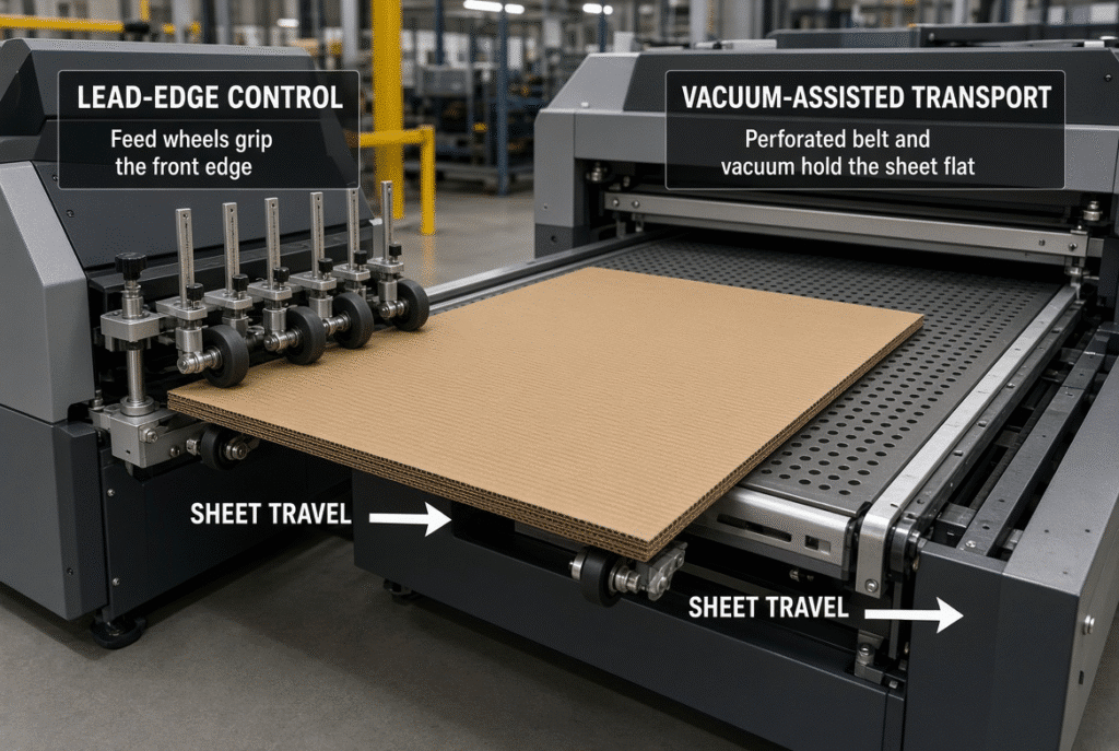
Warp is one of the most critical variables to consider when selecting feeders, and both systems are not the suitable solution in cases of severe warp. Warp is caused by bowing, twisting, edge curl, moisture variation, storage pressure, printing and lamination.
Lead Edge Feeding and Warped Sheets
A warped sheet can lead to uneven front-edge contact, delayed arrival, skew, or edge catching due to a lack of feed-wheel contact. Moderate warp can be handled more easily with proper sheet support, wheel alignment, guide clearance, and controlled speed. The material and machine still need to be reviewed if they have been severely deformed.
Bottom Suction Feeding and Warped Sheets
A warp can decrease contact with the suction area, cause air leakage and/or cause uneven pick up and transport. The result is affected by the suction-zone design, belt support, vacuum stability, stiffness of the sheet and board porosity. Vacuum is not a cure-all remedy for board warp.
Severe Warp Requires Material and Machine Review
Either feeder may not be able to operate in the stable state if there is severe bowing, twisting, edge lifting and damaged sheets. Before changing feeder technology, verify storage conditions, moisture content, pile preparation, sheet quality, machine support and sample-test results.
Registration Performance and Sheet Positioning
The complete system, and not the feeder name, determines die-cutting registration. The error in positioning is not random, but must be diagnosed as such.
How Lead Edge Feeding Supports Registration
When necessary, repeatable positioning can be achieved with controlled front-edge arrival, feed-wheel synchronization, front gauges, side gauges, sensors and sheet support when the board and setup is appropriate. This is particularly relevant for printed windows, handles, slots and for close margin requirements.
How Bottom Suction Feeding Supports Registration
When vacuum, belts, support and timing are stable, the transportation of sheets can be done consistently using the suction method. The sheet must still be aligned to good side and forward reference points. There is still potential for variation from leaky vacuum, belt tracking, uneven sheet contact, warped board, and timing.
How to Test Registration Properly
Compare various sheets and registration marks, edges of sheet, die-cut lines, crease lines, windows, handles, side and front margins. Note if there are any errors that are consistent, random, speed-related, or if it is limited to any specific board grade.
Surface Protection for Printed Corrugated Board
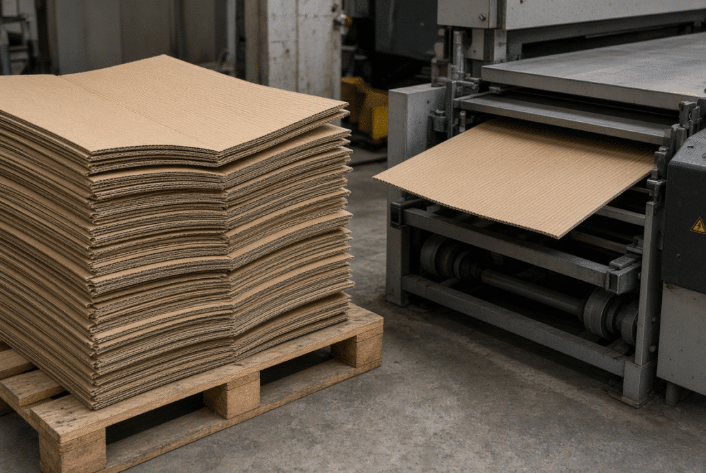
Contact surfaces on printed or laminated surfaces may exhibit scratches, scuffs, pressure marks, gloss changes or ink transfer due to dirty, worn, misaligned or overly tight contact components.
Contact Risks in Lead Edge Feeding
Excessive pressure or contaminated components can damage the face of the printed item or scratch the edge by using feed wheels, brush wheels, guides, belts, or support surfaces. Inspect wheel material, condition, cleanliness, contact pressure and contact area periodically.
Contact Risks in Bottom Suction Feeding
While some contact at the top of the board may be lost, the board still comes in contact with belts, vacuum surfaces, support tables, guides, and delivery components. Quality concerns include dust, obstructed suction holes, belt contamination, and rubbing of the sheets.
Test with Actual Printed or Laminated Samples
Perform a controlled trial with the customer’s actual print surface, coating, varnish, film or litho-laminated board. Check a few of the sheets for scratches, scuffing, ink transfer, pressure marks, gloss changes, and registration shifts before approving the system.
Maintenance and Operating Requirements
Not only is machine capability an issue to be considered but also are the skills, time and spare parts support necessary for maintaining the feeder in a stable condition that plant managers need to evaluate.
Lead Edge Feeder Maintenance
Examine feed wheels, brush wheels, guides, front and side gauges, sensors, support surfaces, belts/transport elements, bearings, drive elements, and lubrication points. Wear is typically seen initially as slipping, skew, surface marks, missed feeds at intervals or registration variation.
Bottom Suction Feeder Maintenance
Check vacuum pump, vacuum hoses, seals, suction belts, vacuum chambers, suction holes, filters, belt tracking, belt tension, sensors and air leakage. A mechanical lead edge system does not necessarily require a higher level of maintenance.
Operator Adjustment and Changeover
Operators do make adjustments when the board grade or the sheet size change, when the flute or thickness change, when the board warp or the surface finish changes. Variability and downtime are minimized with documented job settings, sample trials, safe adjustment procedures, and appropriate training.
Common Feeding Problems in Both Systems
Production issues can occur in both types of feeders. The probable causes may be different, but symptoms on the plant floor may be similar.
Double Feeding
These include sticking sheets, static, incomplete separation, too much pile pressure, surface variation, feed-wheel settings, air or vacuum adjustment, and sensor detection. Diagnosis depends upon the way or the method in which the second sheet is lifted, pulled, or carried with the first sheet.
Skewed Sheets
Skew is caused by uneven contact, misalignment of guides, warping of boards, belt tracking, unequal transport speed, side-gauge pressure, and poor sheet support. Look at the entire route from the pile to the position section.
Missed Feeds
Miss feeds will occur as a result of separation, pickup, vacuum loss, wheel slip, sensor detection, timing or high production speed. A diagnostic sequence which will determine the location of the lost sheet is better than a guess.
Paper Jams
Jams occur at the pile, feeder entrance, transport path, positioning area, or die-cutting handover. Often these are due to warped edges, lack of clearance, poor support, wrong timing or overlapping sheets. Always apply safe stopping and inspection procedures, do not short cut safety systems.
Inconsistent Feed Pitch
Machine cycles, registration and delivery will be influenced by sheet spacing and timing. Pitch consistency is affected by feed-wheel slipping, belt speed variation, vacuum instability, sensor timing, sheet size and machine synchronization.
How to Choose Between the Two Feeding Systems
Map the job profile onto the factors that affect the job, not by feeder name.
Match the Feeder to Board Type
Discuss flute types (E-, B-, C-, and others), single wall and double wall board, board thickness, sheet weight, surface coating, printed or laminated face, typical warp, edge condition, and sheet format. The name of the flute is not enough to specify the material.
Match the Feeder to Production Requirements
Take into account the need for production speed, stable production speed compared to the maximum production speed, acceptable registration tolerance, frequency of job changes, daily production quantity, operator capabilities, maintenance capability, acceptable waste and technical support. It’s more important for the total operating performance than any one specification.
Request a Realistic Sample Test
Test the actual or representative board grade, flute type, sheet size, print or laminated surface, level of warp, die or similar die, and target production speed. Document feeding stability, registration, surface protection, jams, waste, operator intervention and delivery quality.
Questions to Ask the Supplier
- Which board grades have been tested?
- What is the action of the machine on moderate warp?
- Which parts of the sheet are touching it?
- How are double feeds detected?
- What is the procedure for registration?
- What maintenance is to be expected and what parts need to be replaced frequently?
- Which board of them did you achieve a similar speed at?
- Are there references or test data for the supplier?
- What support, installation and training is offered?
D1060Y and Lead Edge Feeding Applications
Manufacturers consider sheet-fed paperboard and corrugated board die-cutting systems, such as the D1060Y lead edge feeding flatbed die cutting machine, when choosing the right die cutting system. Although, the final suitability still needs to be confirmed based on board thickness, flute structure, sheet format, surface treatment, die design, production speed and customer specific testing. Talk about materials and ask for a technical assessment from someone based on representative materials and not automatically accepting any general comparison as appropriate.
Frequently Asked Questions About Feeder Selection
Is a lead edge feeder better than a bottom suction feeder?
There is no one right or wrong. The appropriate system will be determined by the characteristics of the board, the sheet format, the warp, the surface, the registration, speed, machine design, maintenance facilities and sample-test results using the actual material.
Which feeder is better for warped corrugated board?
Serious warping can occur in both systems. Inconsistent contact with front edge may occur in lead edge systems. There can be poor vacuum contact or air leakage in bottom suction systems. Warp is moderate with support and setup, severe with material and machine review.
Which feeder is better for printed corrugated board?
Protection on the surface is based on all contact points, and not on the feeder principle alone. Some upper surface contact may be lost by a bottom suction system but belts, guides, suction surfaces and delivery components will need to be evaluated using actual printed samples.
Does bottom suction feeding improve registration?
With correct vacuum and belts, it can offer stable picking up or transporting. Registration continues to be based on front and side sheet positioning, sheet condition, timing, and die set up.
Can a lead edge feeder process double-wall board?
Suitability will vary with feeder capacity, support, clearance, drive, board thickness and overall machine configuration. Test double wall representative samples beforehand before making a decision.
What causes feeding problems in both systems?
Common causes include the use of board warp, improper stack preparation, damaged edges, improper settings, worn parts, dirty sensors, unstable timing, and machine-material mismatch.
What should I evaluate during a machine test?
Stability, separation of sheets, registration, sheet surface quality, jamming, waste, stability of sheet speed, operator intervention, maintenance needs, die-cutting quality and delivery stacking.
What information should I provide when requesting a quotation?
Sheet size, board thickness, flute type, surface treatment, typical warp, die-cutting size, target speed, requirement of registration, production volume and representative sample.
Summary Guidance – Select the Feeder by Application, Not by Name
The better feeder is the one that provides consistent and predictable performance given the customer’s actual corrugated board and production conditions. Assess material compatibility, feeding stability, registration, surface protection, maintenance, operator adjustment, stable speed and supplier testing support. Don’t select a technical school simply because of the feeder name.