

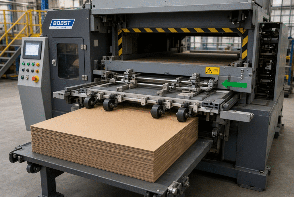
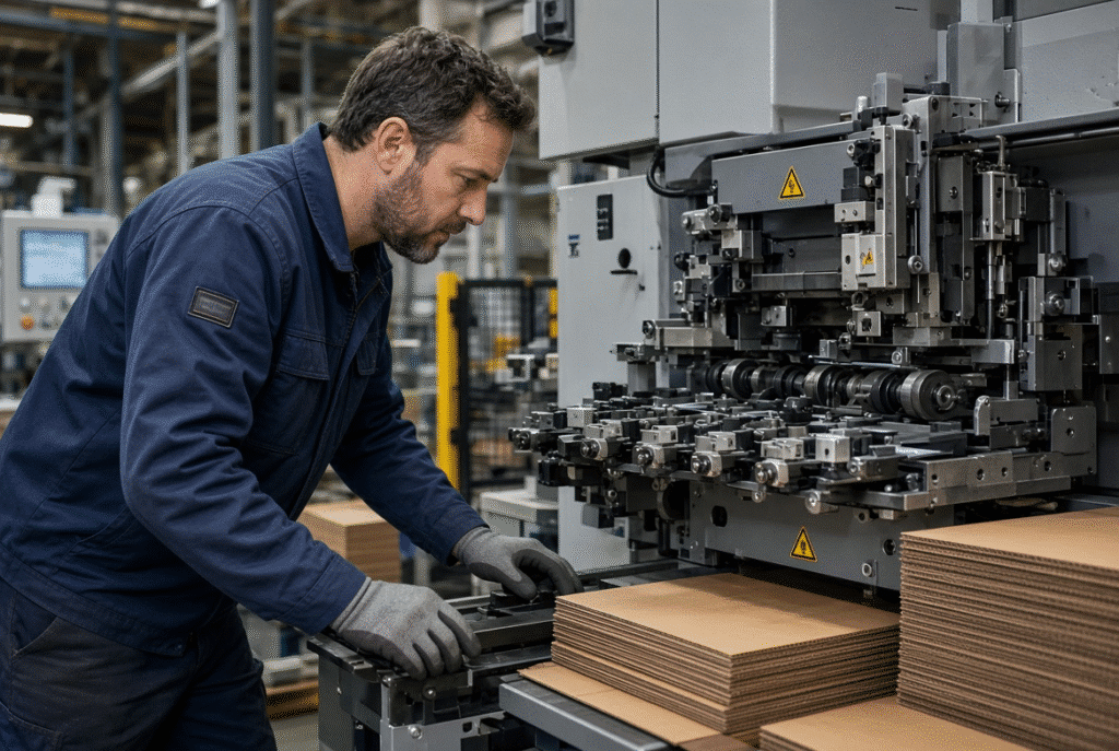
A lead edge feeder controls and moves the front edge of each corrugated sheet from the stack to the positioning and cutting path in a flatbed die cutting machine. It provides sheets at a consistent time and location for the front and side gage to set a consistent reference point prior to the start of the platen cycle. The results still depend on the flatness of boards, structure of flutes, size of sheets, the pressure on the feed wheels, and the surfaces that are supported, the gauge settings, timing of the machine and overall setup.
Corrugated board is more challenging than flat paper or solid board. The ability to engage and guide the lead edge reliably is influenced by large formats, variation of stiffness between flutes, potential for warping from storage or moisture, printed or laminated faces and edge condition. The feeder is not one wheel, it’s one of a coordinated system to handle the handling of the sheet which must work with the other parts of the machine.
What Is a Lead Edge Feeder?
A lead edge feeder is a device used to control the front edge of a sheet (the edge that should be fed into a machine first), advance the edge into the transport and positioning area of a sheet-fed flatbed die cutter. It is a term for describing the way in which front-edge control is achieved, not a specific design. Feed wheels, brush wheels, belts, air or suction assistance, sensors and timing controls are used in various combinations in different machines.
What “Lead Edge” Means in Sheet Feeding
It is just the front edge of the sheet that moves first into the machine that is called the lead edge. Operators observe that this edge comes in right, at a regular pitch (sheet pitch) and in a correct position in relation to the front and side gauges. Problems with the lead edge appear downstream even if the die is mounted properly if its lead edge is late, early, skewed, or damaged.
Lead Edge Feeder as Part of a Complete System
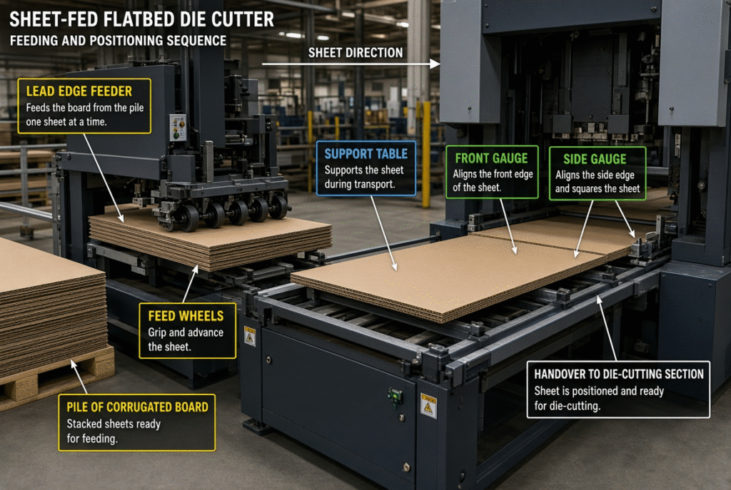
The main drive on the sheet is from feed wheels/belts. Brush wheels or separation devices are used that lift or separate one sheet from the pile. The board is supported to prevent it from sagging or drifting by guides and support tables. Sensors detect the presence and timing. Front and side gauges (or front and side lays) then secure the correct final position before passing it on to the die-cutting area. Each of these risk factors is being addressed by one of these elements.
How a Lead Edge Feeder Works in a Flatbed Die Cutting Machine
The process follows the path of the real sheet on the machine from the stack to the platen. Knowing what happens at each stage will help identify the cause of a feeding problem.
Sheet Separation from the Pile
The machine has to remove one sheet without leaving any parts of it in the stack. Depending on the design, these can be feed wheels pressing on the top sheet, brush wheels, air blasts, suction cups or all of these. Corrugated board may double-feed if sheets adhere to each other by static, high pile pressure, moisture, surface coatings or damaged edges. If the top sheet is warped or is not stacked an even stack it will make it more likely that two sheets will leave as a result.
Lead-Edge Engagement and Sheet Transfer
Feeding components separate and then pull or push the front edge of the sheet into the transport path. Movement should be possible at a high enough contact pressure to allow this to happen, but not so high as to crush the flute structure or to create an embossed or printed face. Insufficient wheel pressure can cause the sheet to slip and cause it to be late at the gauges, excessive pressure can leave a shiny track on printed corrugated board or compress the board itself.
Sheet Support During Transport
Large corrugated sheets require constant support during their transport from corrugated pile to positioning area. A sheet of paper can be lifted off the table, may not touch a feed wheel, or may get caught in a guide. Operators do a visual inspection of support tables, belts, transition points, debris, gaps between the different sections, and guide clearance to keep the sheet flat and controlled.
Positioning with Front and Side Gauges
Front gauges (or front lays) halt the sheet at a given longitudinal reference. Side gauges (or side lays) move the sheet to a set lateral reference point. These gauges set the base line for the die-cutting cycle. A slight mistake here results in uneven margins, misaligned windows, creases that are out of place, misaligned slots, or different blank dimensions.
Handover to the Die-Cutting Section
The sheet should be delivered at the right time and place, to the machine cycle. The feeder speed, sheet pitch, sensor detection, platen action and sheet travel must be synchronized. Even a mechanically sound feeder will not perform well if the setting on the sheets or their gauge positions or the die alignment is off.
Why Corrugated Board Requires Controlled Lead Edge Feeding
Corrugated board is fluted, is not as stiff as most flat board, is compressible, and has a higher tendency to warp than most flat board. These properties directly affect separation, transport, positioning, registration and surface protection.
Warp, Bowing and Twisting
During moisture variation, storage or lamination, or cutting, a sheet can become bowed, twisted or curled at the edges. If a large sheet has a hole or a part of it is suspended during transfer, it may not be in contact with one of the feed wheels or reach the front gauge on time. This translates into some timing or a bit of twist being created that can be seen as registering variation.
Flute Structure and Sheet Stiffness
The characteristics of e-flute, b-flute, c-flute and double wall boards are different. Thinner, flatter boards can slip under light wheel pressure, while stiffer or thicker boards may be more difficult to separate and/or more difficult to achieve the required contact force. Compressibility also varies. It is always necessary to verify machine suitability on the actual thickness of the board, type of flute, size of sheet and manufacturer’s-approved material range.
Printed and Laminated Surfaces
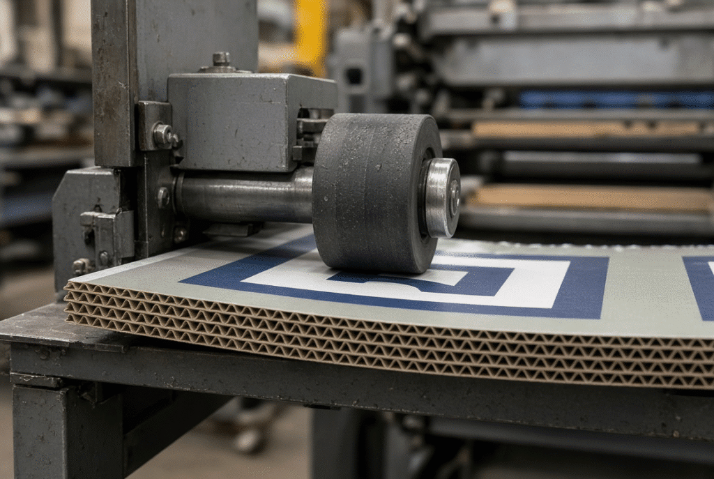
When contact components are worn, dirty or too tight, printed, coated, varnished or laminated faces can suffer from scuffing, pressure marks, ink transfer or gloss changes. The surface protection by the wheel during lead edge feeding does not always result in mark-free feeding, but is dependent on the wheel material, the pressure, the cleanliness of the wheel, the support of the sheet and the transport path as a whole.
Main Components of a Lead Edge Feeding System
Every component has a purpose of addressing a particular handling issue. Recognizable symptoms will result from wear or improper adjustment.
Feed Wheels
The main driving force on the sheet is provided by feed wheels. These are all important: Material, surface condition, pressure, alignment, contact position. Worn or glazed wheels result in missed feeds and slipping. Skew or inconsistent feed length will result from uneven pressure or misalignment. Excessive pressure is indicated by the board or compressing the flute.
Brush Wheels and Separation Components
The separation and stabilization of sheets are accomplished by using brush wheels or other tools. The settings need to be identical in thickness, stiffness, surface and stack. Excessive contact can cause damage or slow down the sheet and a lack of contact can result in double feeding.
Sheet Guides and Support Surfaces
Guides, tables, belts and support surfaces maintain the board’s direction. They should not cause too much friction or edge damage to the sheet. Routine check points include parallelism, cleanliness, wear, support gaps and transition areas.
Sensors and Feed Timing
Sheet presence, spacing and timing are monitored by photoelectric or equivalent sensors. Sensors provide control information, but cannot correct poor support, severe warps, and mechanical misalignment. False alarms or missed detection occur commonly due to dirty lenses, incorrect height, dark or shiny printed surfaces, or mistimed signals.
Front and Side Gauges
Final reference position is set by gauges. Accuracy is influenced by the gauge location, pressure, parallelism, sheet-edge condition and adjustment for sheet size. A slight misalignment of these items translates to an obvious error on windows, slots, graphics and creasing lines.
How Lead Edge Feeding Affects Die-Cutting Registration
Registration is the matching up of the sheet, any printed design, the cutting and creasing guidelines, and the finished blank. Feeding is one component of the system. Good registration cannot be guaranteed by stable feeding in all board and die conditions, with a certain accuracy figure.
Skewed Sheets and Uneven Margins
When a sheet is fed at an angle, it will result in a sheet with non-even margins, cut out positions, crease positions, and blank sizes are not consistent from sheet to sheet. Skew can come from the feeder (uneven wheel contact or guide settings), the board (warp or damaged edges) or later in the process (side-gauge pressure or die alignment). When comparing operator-side and drive-side, it helps to isolate the source without making any die adjustment.
Feed Pitch and Cycle Timing
Cyclic flatbed die cutter requires perfect sheet spacing and arrival time. Waste and loss of effective speed is caused by delayed sheets, overlapping sheets, empty cycles, or feed alarms. A machine operating well at low speed can become unstable as soon as the speed increases, since the feeder and gauges are not able to stabilize the machine if there are small variations.
Diagnosing Registration Variation
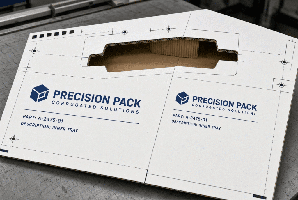
Operators should use the edges of the sheets, printed marks, die-cut edges, creasing lines, windows and side margins to compare several consecutive sheets. When there is consistent offset, it may be due to positioning or die alignment. The most common random variation is one of feeding, warp, separation or material inconsistency.
Common Lead Edge Feeder Problems and First Checks
Several causes may lead to the same symptom being exhibited. The safety procedures and lock-out requirements of the machine should always be followed prior to mechanical inspection.
Double Feeding
Two or more sheets are removed at the same time. These can include static, sticking sheets, too much pile pressure, bad separation settings, incorrect brush pressure, uneven edges, moisture and surface variation. Before increasing contact pressure, verify the alignment of the stacks, separation setting, condition of the feed-wheels, sensor response, and quality of the boards.
Skewed Sheets
Improper wheel contact, guide misalignment, inconsistent transport speed, board warp, damaged edges or incorrect side gauge pressure can cause rotation of the sheet. Check movement on both sides of the machine and make sure mechanical alignment is OK before changing the position of the die.
Missed Feeds
A sheet may be lost when separating, engaging at the lead edge, in transit, during sensor detection or due to lack of timing. Inquire about the last place the sheet was found. These are caused by slipping on the feed wheels, too much warp, damaged lead edges, contaminated sensors, incorrect timing, and production speed that is higher than what the board and setup can currently handle.
Paper Jams
The place of first contact has more value than the place of the first operator detection of the jam. Jams can be on the pile, feeder entry, positioning area or die cutting handover. Stop and isolate energy if necessary, remove the sheet carefully, check the first point of contact, resume under control.
Surface Marks
Printed or laminated board may be marked with dirty or worn wheels, rough guides, excessive contact pressure, adhesion or rubbing of the sheet with the other sheet. Check the entire contact path and compare the position of mark on several pieces of paper.
Practical Setup and Maintenance Checks
It is easier to prevent reoccurrence of problems than repeated emergency adjustments.
Before Starting a New Job
Check the size and thickness of the sheet, flute type, visible board warp, the alignment of the stack, feed-wheel pressure, brush or separation setting, the position of the front and side gauges, the cleanliness of the sensor, intended machine speed, die-cutting handover timing and the condition of any printed or laminated surface. All settings should be based on the board to be run, not the last board run.
During the First Trial Sheets
Check the sheet separation, lead-edge arrival and the sheet spacing, skew, sheet positioning on the gauges, surface marks, die-cutting registration, edge damage and delivery alignment. Change one thing at a time, and note the outcome; this way, the change will be apparent.
Routine Cleaning and Wear Inspection
Accumulated dirt and wear are cleaned and inspected on feed wheels, brushes, belts, guides, support surfaces, sensors, bearings, drive parts, lubrication points and any visible fasteners in compliance with the machine design. However, the signs of wear are often first noticed as intermittent slipping, registration variation or surface marking before complete failure.
When to Reduce Speed or Stop
Clearly, repeated double feeding, increased jams, the need for manual interventions on each sheet, surface damage, feed-wheel slipping, sensor alarms, abnormal noises, edge crushing are all signs. It’s more important to have stable output and safe operation than a nominal maximum speed.
How to Evaluate a Lead Edge Feeding Flatbed Die Cutter
Choosing equipment because of its name, or just its maximum speed is not enough. Complete machine should be identical to board and job profile.
Match the Machine to Your Board and Job Profile
Make the minimum and maximum sheet size, minimum and maximum die cutting size, board thickness range, flute structure, single-wall or double-wall needed, printed or laminated surface, typical warp condition, edge quality, expected production speed, registration requirement, daily volume and specific die cutting and creasing requirements. A nominal maximum and/or nominal speed does not necessarily mean suitability for all corrugated applications.
Questions to Ask the Machine Supplier
- What are the grades of corrugated board that have been tested on this model?
- What does the feeder do to accommodate moderate warp?
- Which parts come in contact with the printing surface?
- How to find and prevent double feeds?
- What is used to correct skewed sheets?
- What thickness and size of board is supported and what format of sheets?
- What are the settings that an operator can change in production?
- How long did it take to produce the same number of boards on the same machine?
- Is it possible to sample customer product and conduct testing by the supplier?
- Installation, training, spares and service support available?
Reference the DAIS D1060Y Naturally
When considering flatbed die cutting for corrugated board, manufacturers considering the purchase of such equipment may take a closer look at the DAIS D1060Y flatbed die cutting machine that feeds the lead edge. Always check final suitability based on the actual board construction, sheet size, die size, and production conditions.
Frequently Asked Questions About Lead Edge Feeders
What does a lead edge feeder do?
It separates and moves the front edge of each sheet to the feeding and positioning path to enable the sheet to be registered prior to the start of die cutting.
Is a lead edge feeder suitable for corrugated board?
It can be applicable provided that the machine has been designed and configured for the desired thickness of boards, flute structure, type of sheet, surface condition and production rate. Testing is used to verify suitability, not by the feeder name.
Does lead edge feeding prevent paper jams?
It will maintain the stability of feeding, but it cannot solve the problems of jamming of the machine due to severe warp, poor stacking, edge damage, wear, improper settings, or machine and material mismatching.
What is the difference between lead edge feeding and bottom suction feeding?
Feed the front edge of the sheet is called lead edge feeding. Bottom suction feeding is the lifting or transporting of the sheet from the bottom through vacuum. A few machines use a mixture of both principles.
Can lead edge feeding protect printed or laminated surfaces?
Surface protection is various and depends on wheel material, contact pressure, alignment, cleanliness, sheet support, board condition and the entire transport path. Under all conditions, no feeder is automatically mark free.
Why are sheets entering the die cutter skewed?
These are typically related to feed-wheel alignment, guide settings, board warp, damaged edges, side-gauge pressure, machine timing and uneven support. The source should be determined first before the die is adjusted.
What information should I provide when requesting a quotation?
The range of sheet size, types of board, type of flute, thickness, printed or laminated surface, desired speed, die-cutting size, board registration, and board samples.
Should the machine be tested with my own board?
Yes. Printed, laminated, warped, double-wall or unusually thick or high-value packaging material requires testing with actual production board, particularly.
Summary Guidance – Using Lead Edge Feeding Reliably
One element of a complete sheet handling and registration solution is a lead edge feeder. Reliable results are obtained by inspecting the board, making the stack of the board clean and square, setting the feed wheels and guides carefully, verifying the sensors and timing, providing a continuous sheet of support, running out the controlled trial sheets, monitoring registration and surface quality, recording settings for the job and confirming that the machine is suitable for the job by operating with representative sheets of material.
If considering equipment or persistent feeding problems on corrugated board, examine the technical details of the DAIS D1060Y lead edge feeding flatbed die cutting machine or bring your board samples, board formats, die requirements, and production goals to DAIS where they can match the feeder with the actual job conditions.