

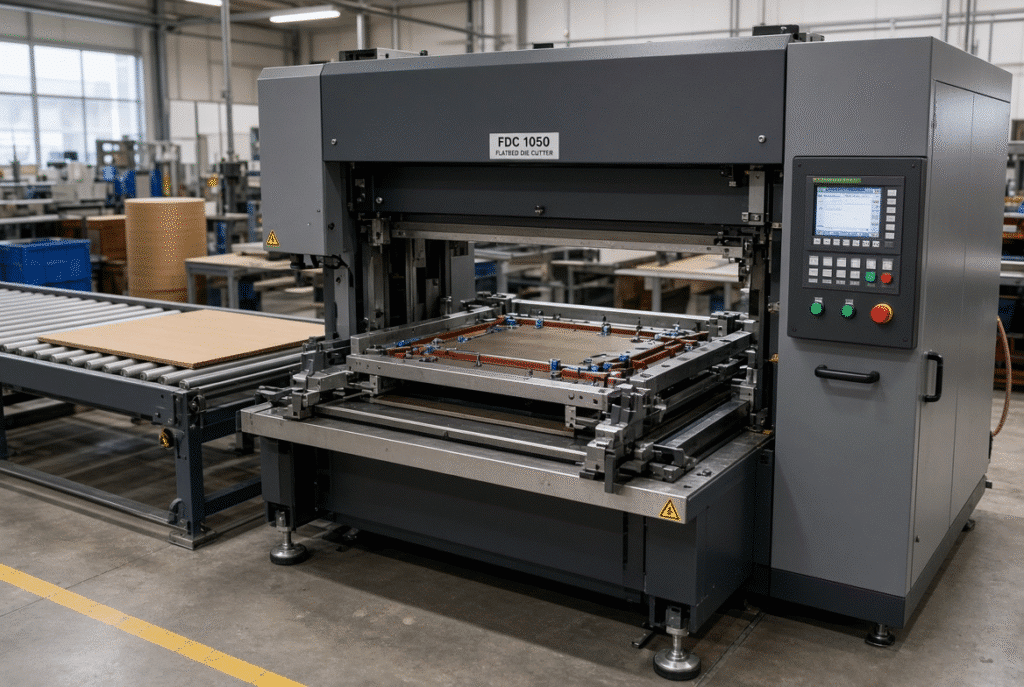
A die cutting chase and a plate frame make up the support structure which secures the steel-rule die and cutting rules and creasing rules to a fixed position within the flatbed or platen die cutter. They usually perform as a job of holding the tooling in place and properly referenced to the platen and sheet to assure consistency in cutting and creasing runs.
Insufficient or incorrect positioning of the chase or plate frame, or insufficient or inadequate fine adjustment, can cause incomplete cuts, registration drift, uneven creasing or repeated pressures on the die even from a well-made die. The reality is that operators often find themselves adding extra makeready time by trying to adjust the pressure or gauges when it is a pressure motion or tooling misalignment problem.
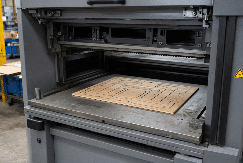
What Are a Die-Cutting Chase and Plate Frame?
The terms used differ among manufacturers and geographical areas. The top support is sometimes referred to as a chase, a plate frame or die-cutting frame. The function of the component in all cases is the same – it is used to receive the die board or the tooling plate, and to serve as locating references and to lock the assembly for production in the machine.
The Role of the Chase
The chase serves as a hardcopy frame of reference. It should be able to withstand repeated compression by the platen without movement, twisting or any movement of the die board. Seats match up with the machine’s locating points when the pressure is more evenly distributed across the cutting and creasing rules. In the chase, any play reveal themselves as unfinished cuts in some place or progressive registration change in prolonged run.
The Role of the Plate Frame
The plate frame is used to hold or support the die board (or cutting plate) when installing and manufacturing. It can include locating edges, intermediate positioning features and the locking points that hold the parts together depending on the machine design that it may have. Many modern flatbed machines include the fine-adjustment mechanism from the make-ready process on the plate frame.
How the Tooling Assembly Fits Together
The steel cutting rules and the creasing rules are imprinted on the die board. Those rules ensue the real cut and crease. The rules are placed on the matrix (or counter-die) which is placed on the lower platen or cutting plate. The chase or plate frame just secures the top tool against the platen and the registered sheet. The frame itself does not cut, but helps to hold the cutting geometry stable, allowing the rules to work.
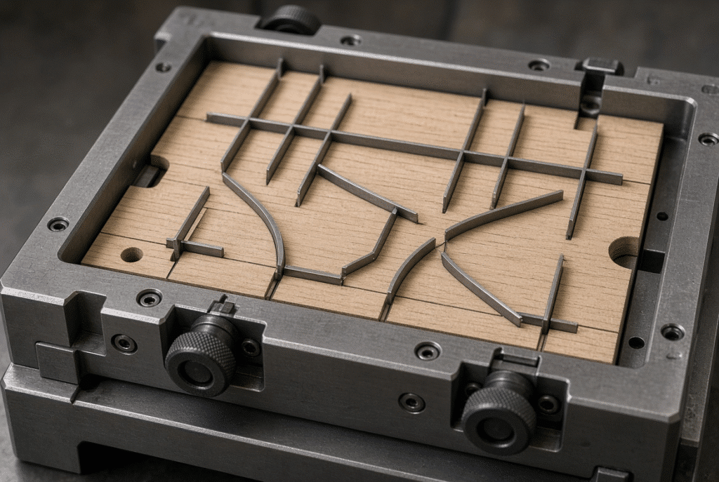
Why Positioning Accuracy Matters in Flatbed Die Cutting
Tooling position differs from sheet registration but both should interact with each other. The cross-sectional area of the die should be positioned in the right relationship to the printed image, the front gauge and the side gauge and the working area of the platen.
Relationship Between Tooling and Sheet Registration
A slight misalignment of a chase or plate frame is apparent on a large sheet or in the layout of a carton. Registration problems, crease lines end up drifting from folds, and the carton sizes don’t end up being within tolerance. Registration is affected by sheet feeding, gripper transport, and gauge and/or material condition, but the tooling frame needs to be in an accurately known, repeatable position to begin.
Positioning Across the Working Area
The tooling needs to be able to be consistently held in the die-cutting area of the machine. If rules are not placed correctly, they can come close to the edge of the platen, and ensure an uneven pressure or part of a multi-up layout is not in the zone of effective cutting. The maximum sheet size is not the same as maximum die cutting size, and the frame must ensure that the die stays within the pressure bearing area.
Position Repeatability After Die Changes
A good set of locating references and a clean frame minimize variations with each die insertion and removal. Repeatable seating reduces trial sheet count and reduces set up time. Pneumatic locking can aid consistency, but isn’t a replacement for proper initial positioning or a frame that’s not worn or contaminated.
Pneumatic Locking: Function and Practical Benefits
Many of today’s flatbed die cutters have a pneumatic locking mechanism to hold the plate frame or die plate once it is in position.
How Pneumatic Locking Works
After the frame is positioned against the locating references of the machine, controlled air pressure operates locking cylinders or clamps to secure the frame firmly in place. The number of actuators, the sequence of the valves and the direction of locking vary according to the design of the machine. Each type of equipment will have a pneumatic diagram and procedures provided by the operator which must be adhered to.
Why Pneumatic Locking Can Improve Setup
A properly designed pneumatic system can enable frame securing to be quicker and consistent from one operator to another than if it is done manually. The advantage is that clamping force is more uniform and set up is less time consuming, helping to minimize frame movement during the run and reducing makeready.
Pneumatic Locking Is Not a Substitute for Correct Positioning
The frame will be locked wherever it is placed. The tooling is not aligned if the initial seating is incorrect. A damaged locating edge or a warped die board or frame which is not completely seated against its references can not be corrected with clamping force. Never lock without confirmation of position.
Pneumatic Locking Safety Considerations
The pneumatic system shall be safely released and isolated before removing any frames, adjusting or maintenance any tools, as per the machine’s manual. Unexpected movement can occur as a result of stored energy. Guards and interlocks must be in place at all times. Do not enter platen or tooling area when the machine is powered up or can move.
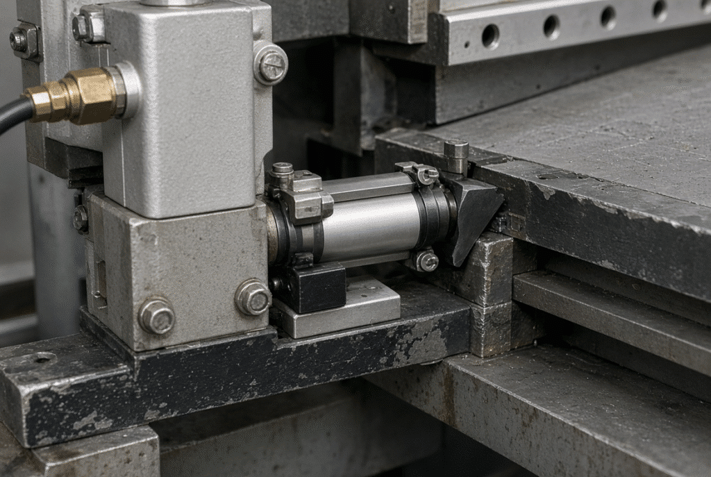
Fine Adjustment During Make-Ready
Fine adjustment is used to make a small controlled adjustment of the position of the tooling after it has been correctly installed and locked after the die is correctly installed and locked. It’s not a panacea for serious issues.
What Fine Adjustment Can Correct
If there are any small offsets in a particular imprinted sheet, or in the crease alignment when compared to the sheet, or if the crease board seats slightly differently in the machine, fine adjustment can compensate for these minor offsets within the machine’s tolerance range. The amount of travel should not be exceeded and varies according to frame design.
What Fine Adjustment Cannot Correct
Fine adjustment is not a solution if a die is warped or incorrectly built, if the rules are worn or loose, if the matrix is damaged, if the frame is extremely loose, if the pressure on the platen is uneven, or if the machine is misaligned. Wasted time and material is wasted by continually tweaking the frame without addressing these root causes.
A Controlled Fine-Adjustment Process
- Verify sheet register and material condition.
- Ensure that the die and frame are properly positioned and locked.
- Perform a small number of controlled sample sheets.
- Estimate the direction and the approximate magnitude of any errors.
- Take one little adjustment in the necessary direction.
- Recheck for completeness of cuts, crease quality and registration.
- Document the final agreed upon setting parameters for the job.
When you make changes, they are much more likely to be accurate if they’re small and documented.
Fine Adjustment and Makeready Waste
The number of trial sheets can be decreased by using accurate references and a usable fine adjustment system. True savings still rely on the quality of the tools and the skill and restraint of the operator and the stability of the material. By identifying makeready sheets by die and product, it is possible to identify recurring frame related waste.
How Incorrect Frame Positioning Appears in Production
Symptoms are signs, not diagnoses. The same defect can be caused by more than one thing.
Print-to-Cut Registration Error
Position of the frame is a possibility if the die keeps rolling past the marks or artwork in one direction. When errors occur and vary, they are likely due to sheet transport, gauges or material movement. Write if the shift is constant, directional or changes with speed.
Incomplete Cutting in One Area
The cause of local incomplete cuts may be due to uneven frame support, incorrect seating of die board or condition of platen and/or pressure distribution. Firstly, a check of local support and alignment should be done before raising the overall pressure.
Inconsistent Creasing
The creasing rules, worn creasing rules, crease placement, and the height of the matrix can all cause uneven creases. Before you suspect the frame, check all the tooling in the stack.
Frame Movement, Vibration or Noise
Any movement or repeated knockings or abnormal vibrations while cutting is a warning sign. STOP machine and notify condition. An unstable tooling assembly can lead to die damage, quality and safety problems which can be costly if the situation continues.
Extended Makeready Time
Many trial sheets or a need to frequently re-lock, or to repeatedly reposition the frame, usually point to worn locating points or incomplete locking, unclear procedures or inconsistent die construction. Setup time per product will be used to identify the pattern.
Common Chase and Plate-Frame Problems
Worn or Damaged Positioning References
The repeated installation, impact or contamination causes stops, guide surfaces and locating edges to wear. Each successive die change will now have the same variation in position as the earlier ones. Repair/replacement is to be done in accordance with the manufacturer’s or die maker’s method.
Incomplete or Uneven Locking
One side or corner can be free while the frame looks locked. Air leakage, wear of the actuators, contamination on actuator contact faces and/or incorrect seating. Avoid running production without a sure lock.
Pneumatic Leakage or Pressure Loss
A leaking tubing, fitting, valve or cylinder may initially lock the lock, and then relax during production, causing it to allow the oil to leak through. Use qualified technicians to repair compressed air and isolate the compressed air prior to any pneumatic service.
Damaged Die Board or Plate
If the die boards are warped, cracked, swollen or damaged, they will not fit flat in the frame. If physically unstable tooling is used, the frame can’t compensate. Before installing any board, inspect it for any defects and any defective tooling should be returned to a qualified die maker.
Contamination Between Contact Surfaces
The result is an uneven pressure and does not allow complete seating because of paper dust, paper scrap, dried adhesive or oil between the frame, die board and locating surfaces. Remove dirt from contact areas using approved method for the material being cleaned; abrasive cleaning may cause damage to precision surfaces.
Installation and Make-Ready Checklist
Inspect the Die and Frame Before Installation
Inspect die board for warping, cracked rules, matrix condition and loose rules. Inspect frame surfaces to check for damage or contamination on the surface, at points and locking components. Wasted sheets and unsafe operation are avoided by locating the problems prior to the tooling being placed in the machine.
Clean and Prepare Contact Surfaces
Faces need to be clean, dry and free of foreign bodies when positioning and locking. False seating that is good until the first pressure cycles, when movement is seen.
Position the Tooling Against the Correct References
Place the frame or die completely against the machine’s approved locating references before locking in any fashion. Avoid using visual approximation.
Lock and Verify
Operate the locking system as per the machine procedure. Verify cues, sitting and no play. Even though the frame is locked, it should be checked for the proper position.
Run Samples and Inspect the Result
Assess the quality of cut completeness, crease quality, print-to-die registration, edge cleanliness and finished carton size in representative material. Document approved settings for repeat jobs.
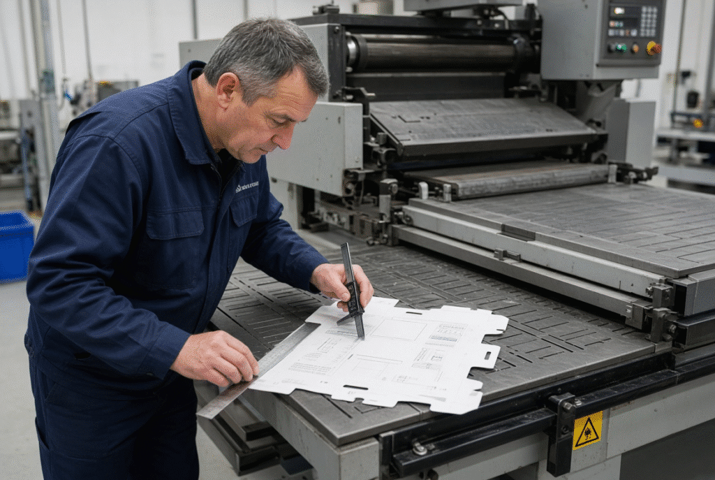
Troubleshooting Positioning and Fine-Adjustment Problems
Determine Whether the Error Is Consistent
If the offset is the same direction, then it may be a frame position or registration setup issue. When there is an intermittent error, it is usually a sign of movement, locking variation, sheet transport or vibration. Record Direction, Approximate Size, Machine Speed and Material.
Check Material and Sheet Transport
The cause of apparent tooling misalignment may be one of several factors, such as curl, warp, feeder problems, gauge setting, or condition of the gripper and/or sensor. Eliminate the following before relocating the frame:
Check Tooling and Matrix Condition
Positioning problems are often caused by worn or loose rules, wrong matrix, damage to the die board or poor make-ready. Evaluate the entire tooling assembly initially.
Make One Adjustment at a Time
Only change 1 variable, re-test and record the outcome. While simultaneous changes make it very difficult to determine which change led to the improvement or the new defect. Do not exceed the machine’s recommended adjustment specifications.
Maintenance of Chases, Plate Frames and Locking Systems
Inspect Frame Surfaces and Locating Points
Regularly check for wear, impact marks, deformation and contamination. Contact surfaces should be appropriate for repeated seating. Damage of the structure or alignment necessitates qualified technical attention.
Maintain Pneumatic Components
Locking reliability is influenced by air quality, filters, tubing, fittings and valves and actuators. Incomplete locking or more time taken to lock indicates low or changing pressure. Adhere to pneumatically planned maintenance schedule.
Check Fasteners and Mechanical Locking Parts
Fasteners and brackets can become loose due to vibrations and repeated frame changes. Do not use torque and/or adjustment values as per the machine documentation.
Protect Frames During Storage and Handling
Properly support, protect from impact and contamination when not in use. The next production problem is an issue when the frames are deformed or dirty.
What to Ask a Flatbed Die Cutter Supplier
Questions About Frame and Tooling Compatibility
- What kinds of die boards or plates can be mounted in the machine?
- What is the tooling positioned to and what locating references are provided?
- Which is the locking mechanism of the frame and what range of fine adjustment does it offer?
- What are the supported and documented tooling change procedures?
Ask for clear drawings and directions for installing the dies that you use.
Questions About Pneumatic Locking
Request locking system, air requirements, safety interlocks, leak monitoring system, maintenance points and manual release. Not just the cylinder is enough to ensure a reliable system, it’s the positioning and locking process as a whole.
Questions About Production Testing
Ask for samples using sample dies, board grades, sheet sizes and printed material. Assess positioning, locking consistency, fine adjustment, cut and crease quality, change over time/repeatability. Simply using an illustration die is not enough.
Chase and Plate-Frame Considerations for the DAIS D1060
Confirm the D1060 Tooling Configuration
The DAIS D1060 semi-automatic flatbed die cutter has a lock mechanism with pneumatic operation to rapidly move and lock the die-plate during set-up. The die-cutting plate frame features an intermediate positioning system and also has a fine-adjustment function to perform controlled correction of set-up. The exact dimensions for the tools, locating details and procedures are provided in the machine’s technical documentation; these should be checked for every installation.
Positioning and Setup for Packaging Production
Repeatable tooling seating and controlled make-ready are advantages of a 1 060 mm machine for paperboard or corrugated sheets. Clean references, reliable locking and disciplined fine adjustment ensure print to cut registration and crease quality is maintained within production tolerances in the typical packaging run.
Service and Documentation
When ordering, ask for installation drawings, tooling instructions, pneumatic diagrams, maintenance schedules and spare parts list. These documents are for both the commissioning of the chase, plate and locking system and for long term use while the system is operated.
Final Guidance: Locking Stability Supports Cutting Consistency
Stable die-tool positioning is provided by the chase and plate frame. If the frame is designed correctly, is cleanly seated and is well-maintained, the setup is repeatable due to pneumatic locking and fine adjustment. Even with good results, there are requirements for accurate tooling, clean contact surfaces, initial correct positioning, reliable locking, controlled adjustment, routine machine care and representative sample testing.
Worried if a flatbed die cutter will meet your tooling and setup needs? Provide DAIS with the following: Die board information, die size, type of board, product layout, and machine requirements. Our technical team will be able to review tooling compatibility, positioning and configuration options.