

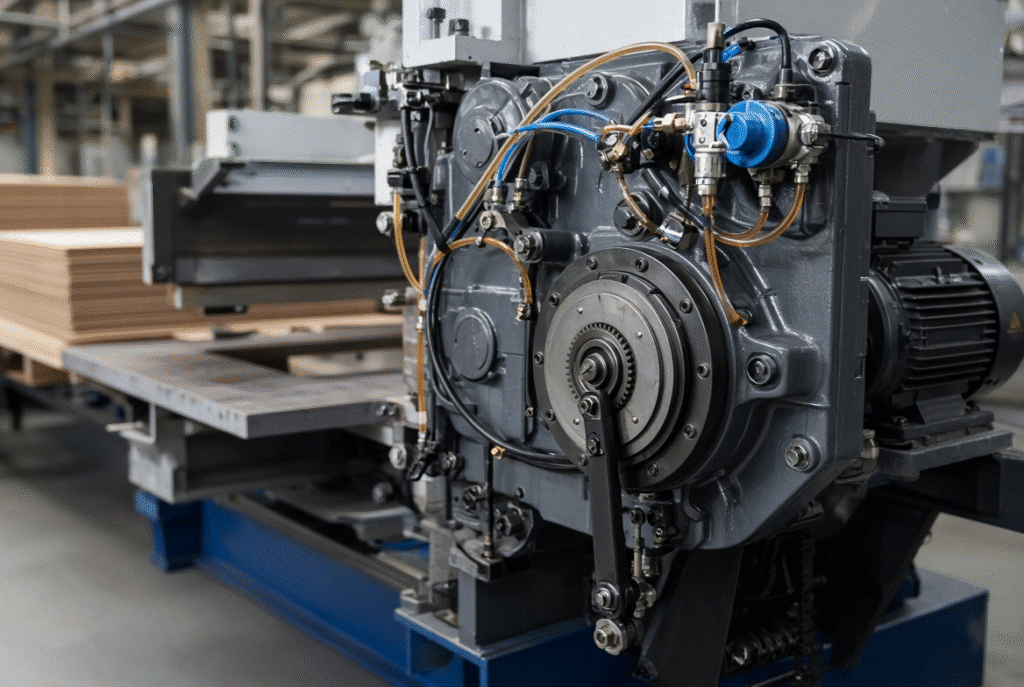
A pneumatic clutch is used to engage and disengage mechanical power in platen die cutting machines to enable the die cutting cycle to start, stop and maintain consistent timing. The clutch or clutch air-control circuit can exhibit delays in engagement, slip under load or fail to release fully, depending on the type of problem that occurs.Depending on the problem, this machine may exhibit delayed engagement, slipping under load or incomplete release from the clutch or its air-control circuit. Failure to inspect the air circuit and transmission and continue to restart the machine without considering secondary damage and safety issues are to be avoided.
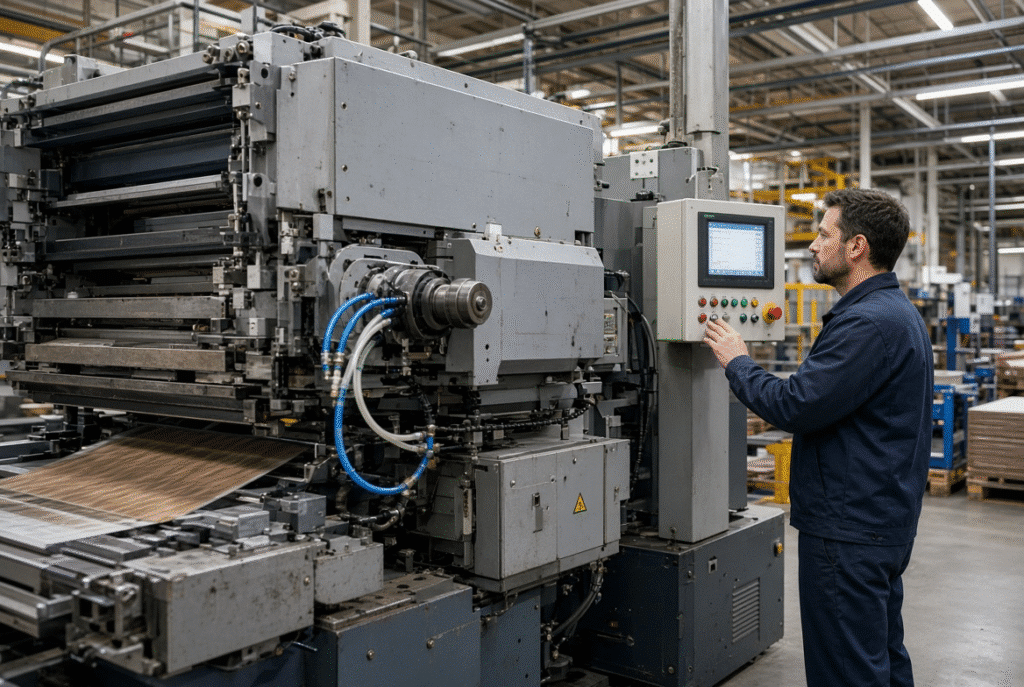
What Is a Pneumatic Clutch in a Platen Die Cutter?
A pneumatic clutch is a mechanical clutch that is operated using compressed air. If the air is properly applied, the clutch transfers torque to the platen, in turn, allowing it to complete its cycle; if the air is released, the drive is disconnected, stopping or coasting the machine, depending on its design.
The specific clutch configurations vary from machine to machine and manufacturer. Several rely on a pneumatic actuator that applies force to friction discs; others feature other mechanical interfaces that are operated by air. Use the following descriptions as a technical overview; refer to the specific machine’s documentation and technical pneumatic schematic for specific parts and pressure before use.
The Basic Function of the Clutch
Clutch is used to transfer or interrupt mechanical power. It needs to respond quickly to commands, operate without excessive slippage, and disengage easily when it is needed for safety or by the system. This has a direct impact on machine start/stop, cycle uniformity and operator interrupts to stop the machine safely. Clutch does not set cutting pressure or sheet registration, these are controlled by the platen, intermittent mechanism and control system.
Pneumatic Control Versus Mechanical Engagement
This system has two parts which need to function as one. The compressed air side includes the compressed air supply, regulator, filter, moisture separator, solenoid valve, tubing and actuator. Mechanical components are the friction surfaces, hubs, shafts, keys, bearings and other transmission components. If the air circuit is restricted, contaminated or leaking, even though all friction components are perfectly serviceable on the machine, the machine will engage slowly or inadequately. On the other hand, a clean air and a responsive valve will not correct worn or contaminated friction surfaces.
Interaction With Machine Safety and Controls
Normally, clutch operation is interlocked with the machine’s cycle logic and emergency stops, guard switches and limit switches. These interlocks help prevent unexpected movement. Safety circuits are never to be shorted around to continue production. A fault that makes the clutch slip or hold up when it is not supposed to, is a safety and maintenance problem not a problem to “work around.
Main Components of a Pneumatic Clutch System
Operators and maintenance staff are faced with a number of elements that can affect clutch behavior. The actual configuration should be checked with the machine’s pneumatic diagram.
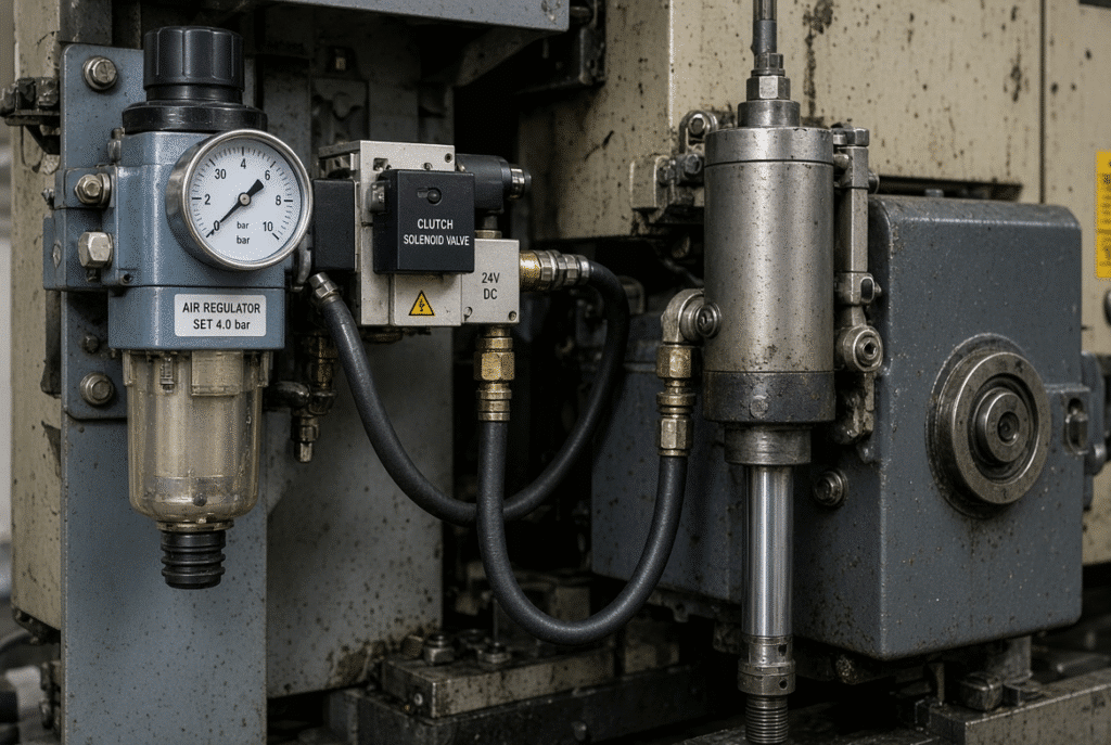
Compressed-Air Supply and Pressure Regulation
The air supply to the clutch must be stable, clean and properly regulated. Slow, partial, or inconsistent engagement may result when the pressure drops below the demand, varies with other equipment sucking air or when the pressure is below the machine’s specification. Factors such as compressor capacity and supply line size are of equal importance to the set compressor pressure at the machine. Don’t use a generic plant pressure; always use the manufacturer’s specified operating range.
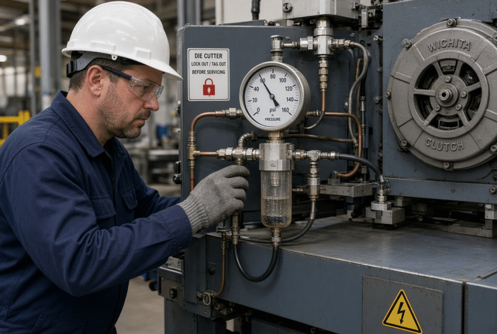
Filter, Moisture Separator and Air Preparation
Filters and moisture separators save valves, seals and actuators from being contaminated with water, oil carry-over and particulate contamination. Valves become stuck, seals deteriorate and response becomes intermittent when wet or dirty air is present. If plants do not prepare the air, the clutch symptoms occur first as sporadic delays that then develop into daily problems.
Solenoid Valves and Control Signals
The control system sends an engage/release signal to a solenoid valve which controls the air to the actuator. The speed and reliability of the valve shift is influenced by electrical supply, coil condition, wiring integrity and/or PLC or relay logic. A possible clutch problem could be in the valve itself or possibly in the clutch control circuit.
Tubing, Fittings and Actuator
Pressure through hoses, fittings and seals to the mechanical clutch actuating pressure. Any amount of leakage will hinder engagement or will not get the pressure to the friction surfaces. Early indications include audible hissing, pressure-gauge drop on command or soft actuator movement. Inspection shall be conducted in accordance to approved isolation procedures.
Mechanical Clutch and Transmission Interface
A mechanical engagement system is operated by the pneumatic actuator. Friction surfaces, bearings, shafts, couplings and similar drive parts are subject to wear when engaged multiple times, contaminated, heated, and improperly adjusted. Mechanical inspection must be undertaken with complete isolation from power and air, guards must be removed in accordance with documented lock-out procedures and should be carried out by qualified technicians.
How the Pneumatic Clutch Works During a Machine Cycle
Although the timing and component placement vary from design to design, the overall sequence is the same in many cases.
Engagement
A signal is sent to the control system and the solenoid valve moves, driving the air to the actuator, which in turn moves the mechanical clutch for the drive. It feels quick and complete to engage the machine in normal situations: no hesitation or audible slip in the start of the cycle. An operator soon gets a feel for how the system should sound and respond.
Power Transmission During the Cycle
When engaged, the clutch should have a minimum amount of slippage and heat transfer, and it should not vibrate. The intermittent mechanism, crankshaft and other parts of the transmission complete the die-cutting stroke. The clutch is merely a part of that chain, and it has one single task: to ensure reliable power delivery; it isn’t responsible for controlling the pressure or timing the sheet.
Disengagement and Controlled Stopping
At the end of the cycle, when an emergency stop is activated or the control system provides a “release” signal, the valve opens to discharge air and the clutch releases. If release is not complete it may leave residual drive, drag, slow down the next cycle or motion after stop command. Before restarting production, any abnormal stopping behaviour needs to be investigated.
Wear Symptoms and What Operators May Notice
Most issues with clutch typically start to show themselves on the machine as a change in machine behaviour that operators can notice and document.
Delayed Engagement
Time to start up after command (or response) becomes inconsistent and/or takes longer than usual from cycle to cycle. There are a number of possibilities: leakage, low or irregular air pressure, slow valve response, contaminated air, wear or control delay of the actuator. Before making the assumption of a friction-surface wear, compare the symptom to the pressure gauge reading at the time of command and to other pneumatic functions on the machine.
Slipping Under Load
Slip can manifest itself in any of the following ways: Incomplete power transmission, speed fluctuation during stroke, heat, burning odor, abnormal noise, or failure to complete the stroke. The causes are worn or contaminated friction surfaces, inadequate air force at the actuator, mechanical damage or wrong adjustment. If the clutch continues to slip under load, additional damage may be caused to the friction surfaces and to other components of the transmission.
Incomplete Disengagement
Residual drag, delayed stopping, continuing moving after a stop command, abnormal resistance at the start of the next cycle or difficulty in restarting are all symptoms. These can include: actuator return issues, valve issues, air pressure, mechanical binding or misadjustment. This is a safety critical condition and needs to be addressed immediately for incomplete disengagement.
Air Leakage and Pressure Loss
Tubing, fittings, seals, valves or actuators that leak decrease the pressure available at the clutch. Slow engagement is a precursor to failure to engage under load, and is usually the first sign of a small leak. Use approved leak-checking methods – never put hands near pressurized leaks.
Abnormal Noise, Heat or Odor
If the grinding, squealing, knocking, clutch housing overheating or burning smell are recognized, the friction surfaces or related bearings and shafts are stressed abnormally. Operators should shut down the machine as per the plant procedure, and not increase pressure or restart repeatedly, but rather report the condition.
Intermittent Stops or Clutch Alarms
Intermittent faults can be caused by pressure instability, electrical signals, sensor feedback, valve sticking, loose wiring or progressive mechanical wear. Keeping an accurate record of the conditions (startup, higher speed, under load, after warm up, after a die change, etc.) will help to pare down the search.
Common Causes of Pneumatic Clutch Problems
Symptoms with a face of clutch failure are frequently caused by other issues. A systematic approach to the air supply, pneumatics, electrical controls and mechanical wear allows for the prevention of replacing a wrong part.
Poor Air Quality and Moisture
Valves, seals and actuators are compromised by water, oil contamination and particles. Sticking, corrosion and unstable response happens if air is wet. It is often more useful to inspect the plant air-treatment system and maintenance logs before opening the clutch.
Incorrect or Unstable Air Pressure
If the pressure is too low, is not stable when load is applied or is not properly set, full engagement is not achieved. Too much pressure may cause seals and parts to be stressed. Never use a generic plant pressure, always use the machine’s approved pressure specification.
Valve, Tubing and Seal Wear
Delayed engagement or leaks are caused by sticking solenoids, damaged tubing, loose fittings and worn seals. These parts can be less costly than a clutch assembly, but can result in the same symptoms. Employ pneumatics schematic and qualified testing procedures.
Mechanical Friction-Surface Wear
Friction surfaces are worn by repeated engagement cycles, excessive slip, contamination, heat or improper adjustment. As time goes on, the machine might need more engagement time, or it may lose load capacity. Replacement cycle and wear limits are dependent upon the machine and should be obtained from the manufacturer’s documentation.
Control, Sensor and Wiring Faults
The clutch could be mechanically strong, but the control system might not be strong enough, or it could provide a partial or lagging or unstable command. This can include wiring, relays, limit switches, and/or PLC logic or safety interlocks. Only qualified personnel should be used for electrical diagnosis; circuits should not be bypassed.
Preventive Maintenance for Pneumatic Clutch Systems
This sensible approach distinguishes between everyday observations made by an operator and routine pneumatic operations and mechanical checks carried out by a technician.
Daily Operator Checks
Be alert for abnormal engagement delay, unusual noise, audible air leakage, repeated alarms, unexpected pressure-gauge behaviour, delayed stopping, vibration, heat or odor, and unexpected cycle response. Note it on the symptoms and shut it down when it is unsafe or when it happens again.
Weekly Air-System Checks
Check air filters, moisture separators, drains, regulators, visible tubing and fittings and valve condition in accordance with plant and machine maintenance schedule. Do not isolate and authorize pressurized components.
Monthly Functional Checks
Engagement and release response is reviewed, pressure stability under operating conditions, valve operation, actuator movement, alarm history and leakage are reviewed by qualified maintenance personnel. Not arbitrary time or pressure limits but the machine’s approved specification and the plant’s historical baseline should be used to compare against the results.
Mechanical Clutch Inspection
Technicians check friction surfaces, actuator linkage, shafts, bearings, couplings, fasteners and other transmission components for contamination, heat damage, looseness and wear. Guards are only removed when the conditions for isolation and lock-out have been approved.
Record Symptoms and Repairs
Record: Log clutch alarm, pressure readings, repairs, parts changes, operating hours, symptoms and job conditions. A good history can be used to identify recurring leakage, recurrent valve issues or progressive valve wear much earlier than they cause a larger failure that prevents production.
Compressed-Air Quality and System Maintenance
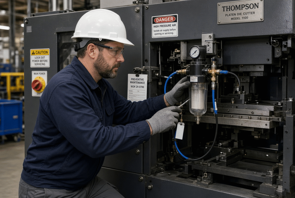
If the plant air supply is unstable or contaminated, the pneumatic clutch will not perform in a consistent manner. The factory’s compressed-air system is directly related to machine reliability.
Air Pressure Stability
Clutch response is influenced by compressor capacity, simultaneous demand of other equipment, undersized lines, regulator condition and pressure drop along the piping. Test pressure at the connection to the machine during normal machine load, not just during idle time.
Moisture Drainage and Filtration
The air-prep equipment manufacturer’s and machine maintenance plan schedules are followed by routine draining, filter inspection and moisture control. Damaging valves and seals by water reaching the clutch circuit.
Clean Tubing and Correct Connections
Kinked, damaged, contaminated or improperly connected tubing compromises the flow and response rate. Leakage and physical damage to fittings should be checked. Only use approved replacement tubing and fittings.
Avoiding Contamination During Service
When replacement hoses or valves are being serviced, dirt can enter into sensitive pneumatic parts. Minimizing this risk is achieved through clean tools, capped open lines and documented procedures.
Diagnosing Clutch Problems Without Replacing the Wrong Part
A systematic method avoids unnecessary parts replacement.
Start With the Symptom and Operating Condition
Record exactly when the problem occurs: start-up, stopping, at speed, under load, after warm up, after die change, during a particular product run or after maintenance. The pattern is likely to indicate the pneumatic, mechanical, electrical or set up causes.
Check Air, Control and Mechanical Systems in Order
Verify approved air supply before checking visible air leaks, alarms, valve and control signals, and then, under safe service conditions, open the mechanical clutch and transmission. The course of diagnosis is determined by the machine schematic and a qualified technician.
Separate Clutch Faults From Transmission Faults
The symptoms of clutch failure can be similar to those caused by gears, bearings, crankshaft, intermittent mechanisms and couplings. Instead of replacing a clutch, a complete evaluation of the whole drive system can be performed to save time and money.
How Clutch Condition Affects Platen Die-Cutting Performance
Cycle Timing and Motion Stability
If the engagement is inconsistent or too easy, or if the slip occurs, it can interfere with the timing and smoothness of the machine cycle, resulting in an unstable sheet movement, frequent stopping or an irregular production rhythm. The drive, intermittent mechanism, controls and condition of the machine also affect cycle performance.
Pressure Transmission and Mechanical Loading
If the clutch does not transmit power properly, it may cause the die-cutting mechanism to not complete its stroke. The heat produced by abnormal slip, and the additional load on components, detracts from the machinery’s performance. The clutch maintenance does not ensure the cutting pressure accuracy, but it can ensure a reliable power delivery.
Uptime and Secondary Damage
Final documentation of the machine must be checked to verify that the clutch type, air requirements, control arrangement, safety functions and maintenance points are correct. There are different configurations even within the same model family. Do not assume that all D1060 or similar platen die cutters have the same pneumatic clutch system.
Pneumatic Clutch Considerations for the DAIS D1060
Confirm the Installed Configuration
Clutch type, air requirements, control arrangement, safety functions and maintenance points must be verified from the final documentation for the specific machine. Configurations can differ even within the same model family. Do not assume every D1060 or similar platen die cutter carries an identical pneumatic clutch arrangement.
Include the Clutch in the Maintenance Plan
If a pneumatic clutch is used, the maintenance program should include the same items as the rest of the drive system, as well as air quality, pressure stability, filters, valves, tubing, and actuator response and mechanical clutch condition.
Ask About Service and Spare Parts
When considering service support, inquire about recommended wear parts, like pneumatics and clutches, troubleshooting documentation, service technicians and their recommendations, and typical lead time.
Final Guidance: Treat Clutch Symptoms as Early Warnings
A pneumatic clutch system should engage and release predictably, transmit power without abnormal slip, and operate within the machine’s approved air and control conditions. Clean and stable air, correct pressure, regular leak inspection, valve and tubing checks, safe mechanical inspection, prompt alarm investigation and documented service form the practical foundation of reliability.
Experiencing delayed engagement, clutch slipping, air leakage or irregular machine cycles? Send DAIS your machine model, operating symptoms, air-supply conditions and production requirements. Our technical team can help identify the information needed for a pneumatic clutch or die-cutting system review.